
Unmatched Performance
German-engineered flow conditioning components that define the global benchmark for aerodynamic efficiency and thermal management.
Minimal Resistance
Achieves exceptional flow optimization with a Darcy-Weisbach friction coefficient as low as 0.031 during high-velocity operation.
Integrated Cooling
Integrated hollow-profile geometry facilitates massive heat exchange capabilities, scaling from kW to MW loads without additional energy consumption.
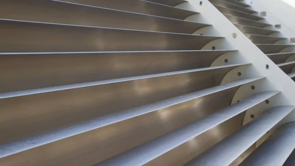
Aerodynamic Design
Precision-engineered airfoil profiles designed to minimize turbulence and significantly reduce pressure loss.
Energy Savings
Optimized aerodynamics lower system resistance, resulting in substantial power consumption reductions.
Technical Specifications
Comprehensive technical data for precise engineering and performance calculations.
Integrated Cooling Technology
Revolutionizing tunnel design, our turning vanes feature integrated internal coolant channels—delivering superior heat exchange efficiency without compromising airflow quality.
- Massive heat dissipation capacity, scalable from hundreds of kilowatts to tens of megawatts.
- Efficient thermal management with zero adverse impact on airflow turbulence or stream quality.
- Engineered with six integrated internal cooling channels per vane for maximum thermal efficiency
- Seamless integration with standard industrial water cooling infrastructures
Applications
Precision-engineered solutions for complex airflow management challenges.
Wind Tunnels
Critical flow guidance for corner sections in high-performance recirculating wind tunnels
HVAC Systems
Maximizing aerodynamic efficiency in large-scale industrial ventilation infrastructures
Industrial Ducts
Optimizing airflow dynamics within complex manufacturing and processing facilities
Heat Exchangers
Integrating precise airflow direction with active thermal management capabilities