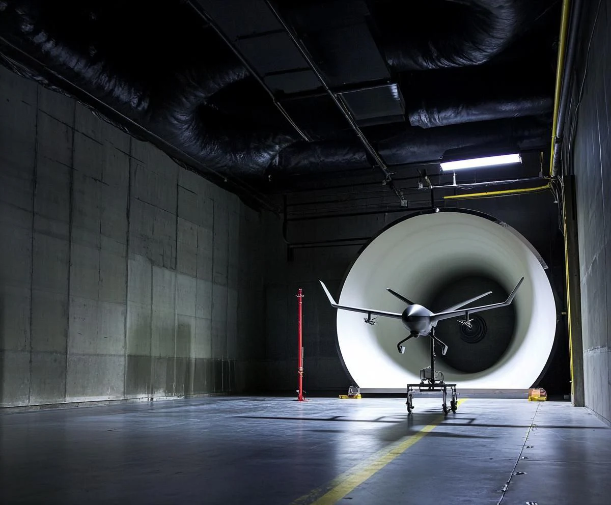
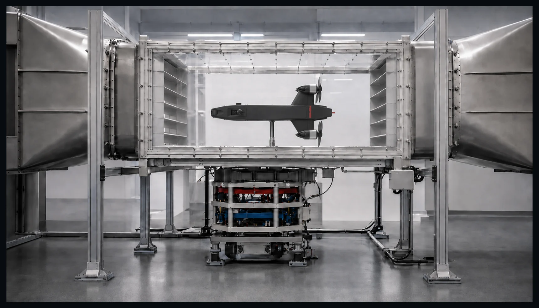
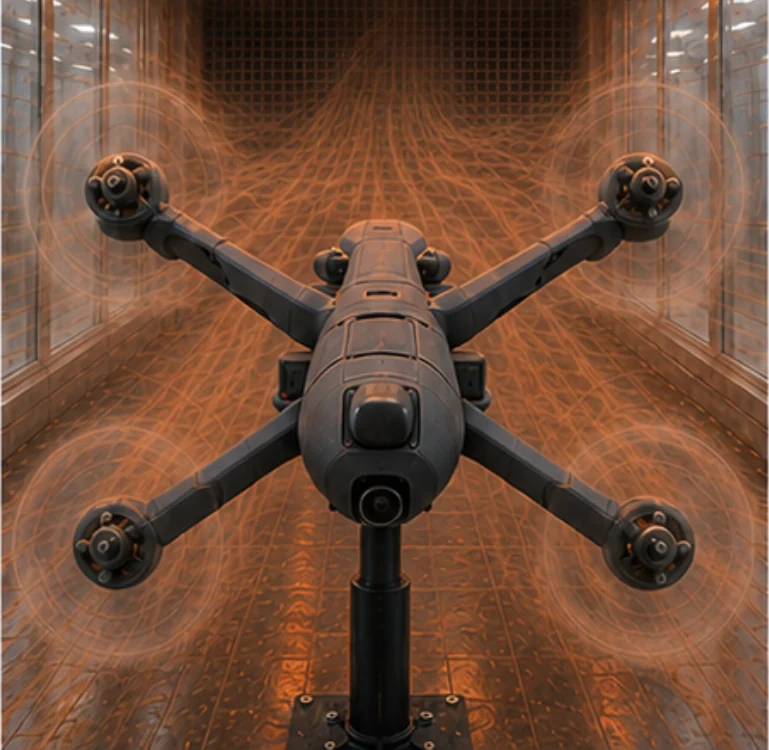
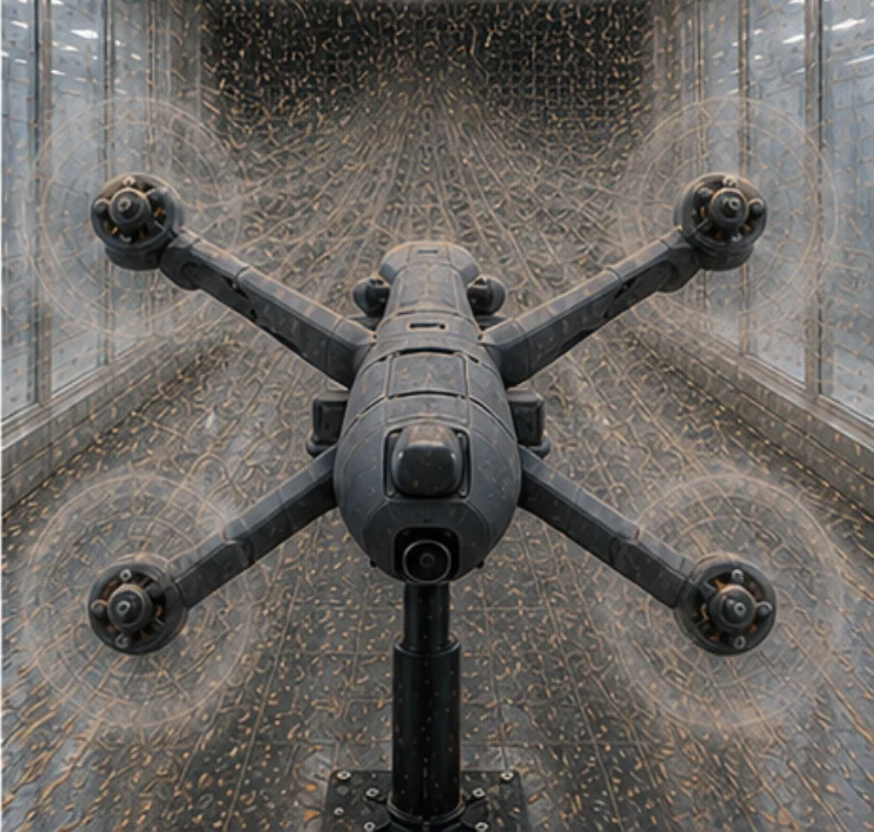
TunnelTech designs custom facilities for complete small UAVs, propulsion systems, components and scaled models of larger unmanned aircraft.
Test-section dimensions, flow conditions, instrumentation and environmental systems are defined by the object you need to test and the evidence you need to obtain.
A scalable test envelope, engineered around the programme
TunnelTech applies its experience in large-scale, high-velocity airflow systems to a new generation of wind tunnels for UAV testing and aerodynamic research.
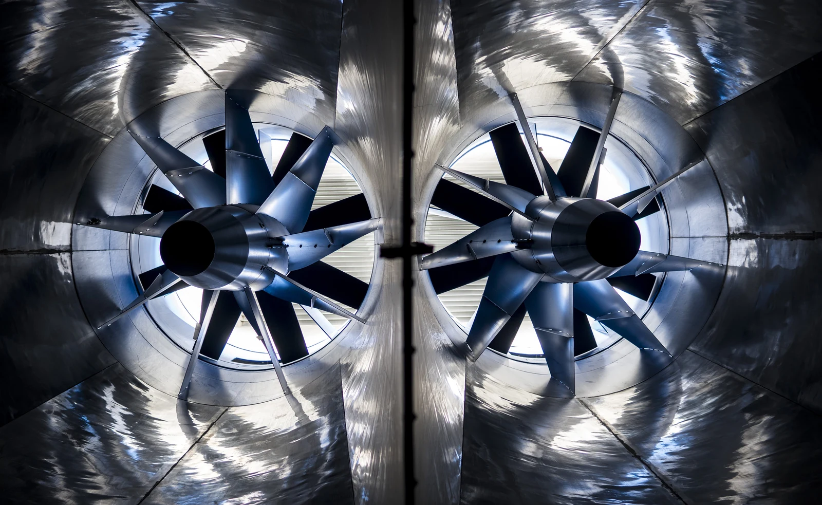
Our indoor skydiving technology already operates with exceptionally large usable airflow volumes at velocities around 300 km/h, including flight chambers up to 6.5 m in diameter. This provides a strong engineering foundation for unmanned aircraft, propulsion-system and aerodynamic-component test facilities.
Operating experienceProven
at industrial scale
01 / Airflow velocity
300+km/h
Proven in operating vertical airflow systems.
02 / Usable airflow diameter
6.5m
Proven flight-chamber scale in delivered technology.
Flow regime / 01
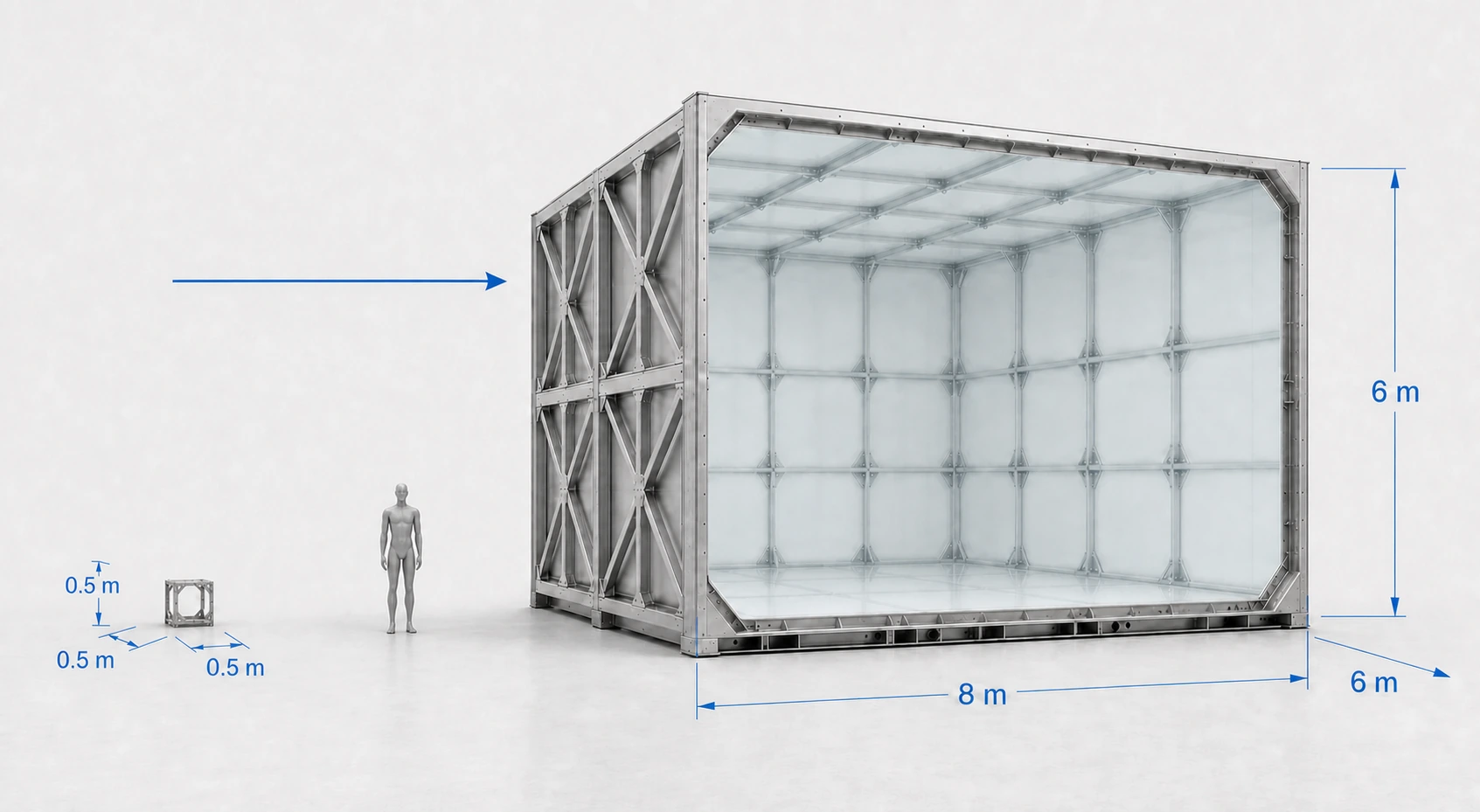
Low-speed wind tunnels
Airspeed0–300km/h
Mach envelopeUp to approximately M 0.25
Test-section range0.5 × 0.5 × 0.5 mto8 × 6 × 6 m
Designed for
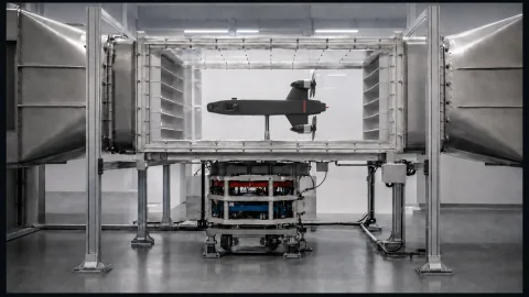
Full-scale UAV testing
Fixed-wing UAVs
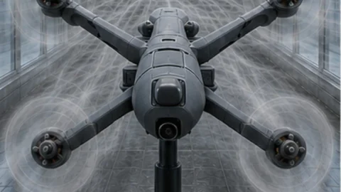
Multirotor and VTOL aircraft
Propeller and propulsion-system testing
Large-scale aerodynamic models
Performance, stability and control studies
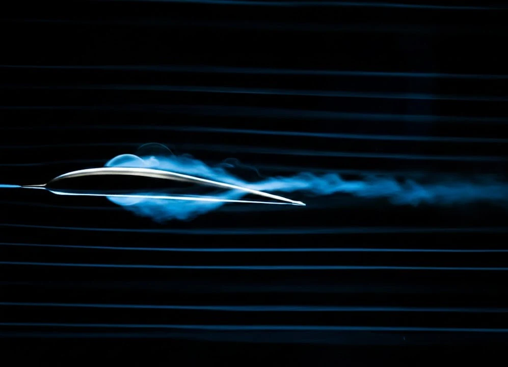
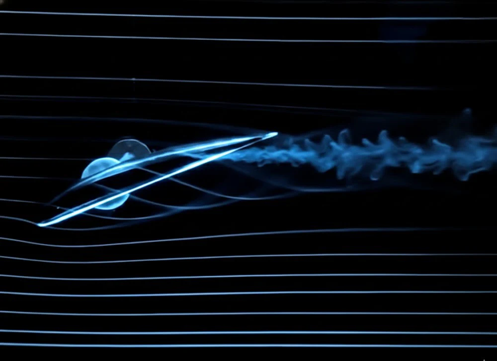
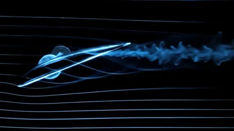
Flow visualization and aerodynamic development
Large test sections allow aircraft to be tested at or close to full scale, reducing model-scale effects and improving Reynolds-number similarity with actual flight conditions.
Flow regime / 02
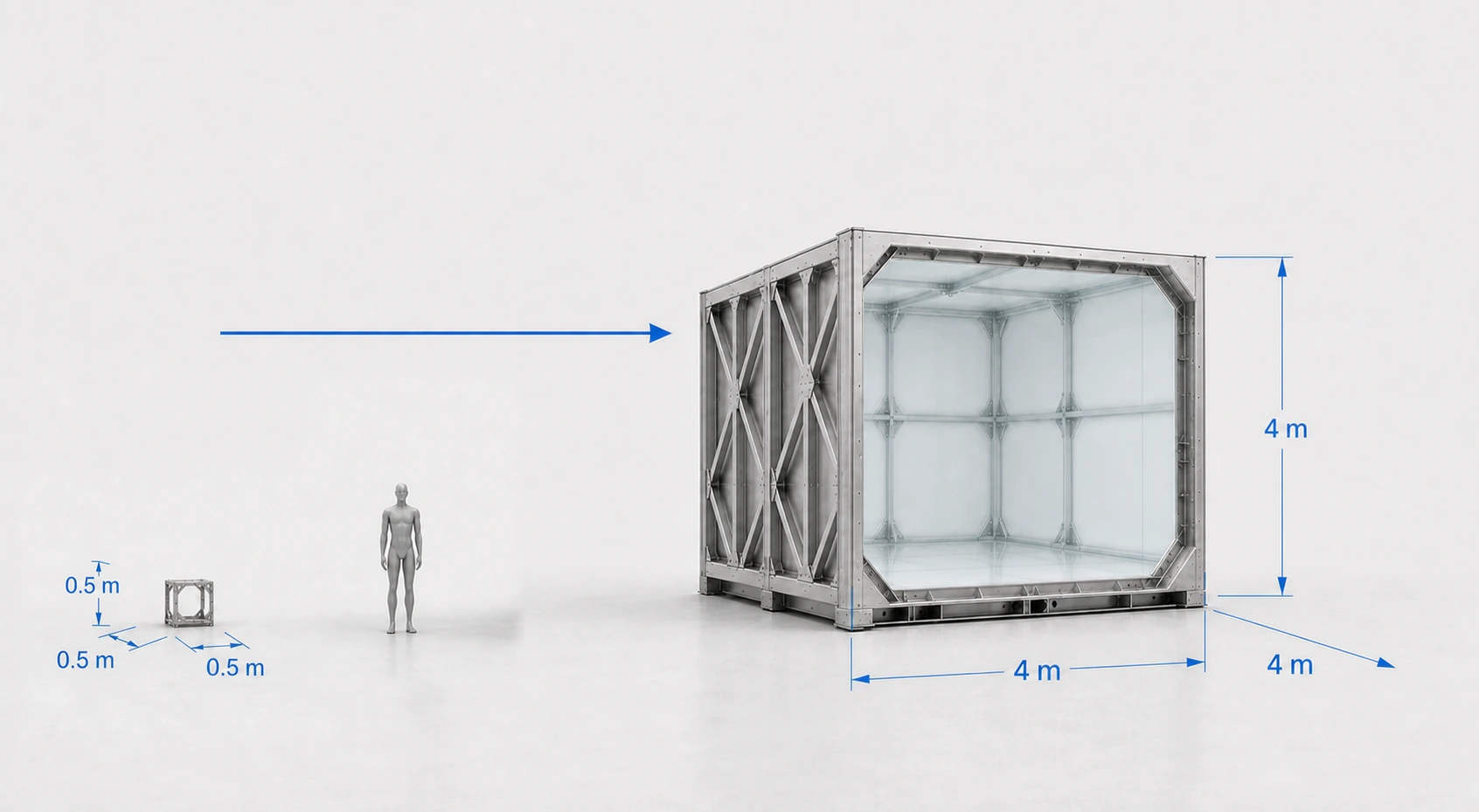
High-speed subsonic wind tunnels
Airspeed300–800km/h
Mach envelopeApproximately M 0.25–0.65
Test-section range0.5 × 0.5 × 0.5 mto4 × 4 × 4 m
Designed for
High-speed UAV development
Scaled and full-size UAV testing
High-subsonic aerodynamic research
Wing, fuselage and control-surface development
Propulsion and air-intake testing
Aerodynamic component testing
High-speed stability and performance studies
Test-section dimensions and maximum velocity are closely interconnected. Power demand, aerodynamic loads and flow-conditioning requirements increase rapidly with airspeed, so each facility is optimized around the required size, velocity and flow quality.
Both scale comparisons use the same 1.8 m human figure, so the two test-section envelopes can be read against each other directly.
Indicative engineering envelope, not a catalogue specification. Maximum airspeed, largest test-section dimensions and Mach range are not necessarily available simultaneously. Final performance depends on test-section geometry, circuit configuration, ambient conditions, power and required flow quality.
Large-scale airflow / core competence
Large airflow is the foundation. Measurement quality defines the research facility.
Wind tunnels for aerodynamic testing and wind tunnels for human flight have different engineering requirements. TunnelTech's existing large-volume airflow expertise provides the engineering basis; the research tunnel is then developed around measurement-grade flow and calibration requirements.
Low turbulence intensityHigh velocity uniformityLow flow angularityControlled static-pressure gradientsBoundary-layer managementLow wall interferenceAccurate force and moment measurementRepeatable calibration conditions
From compact R&D tunnels to large full-aircraft facilities, each system is engineered around the customer's required test envelope.
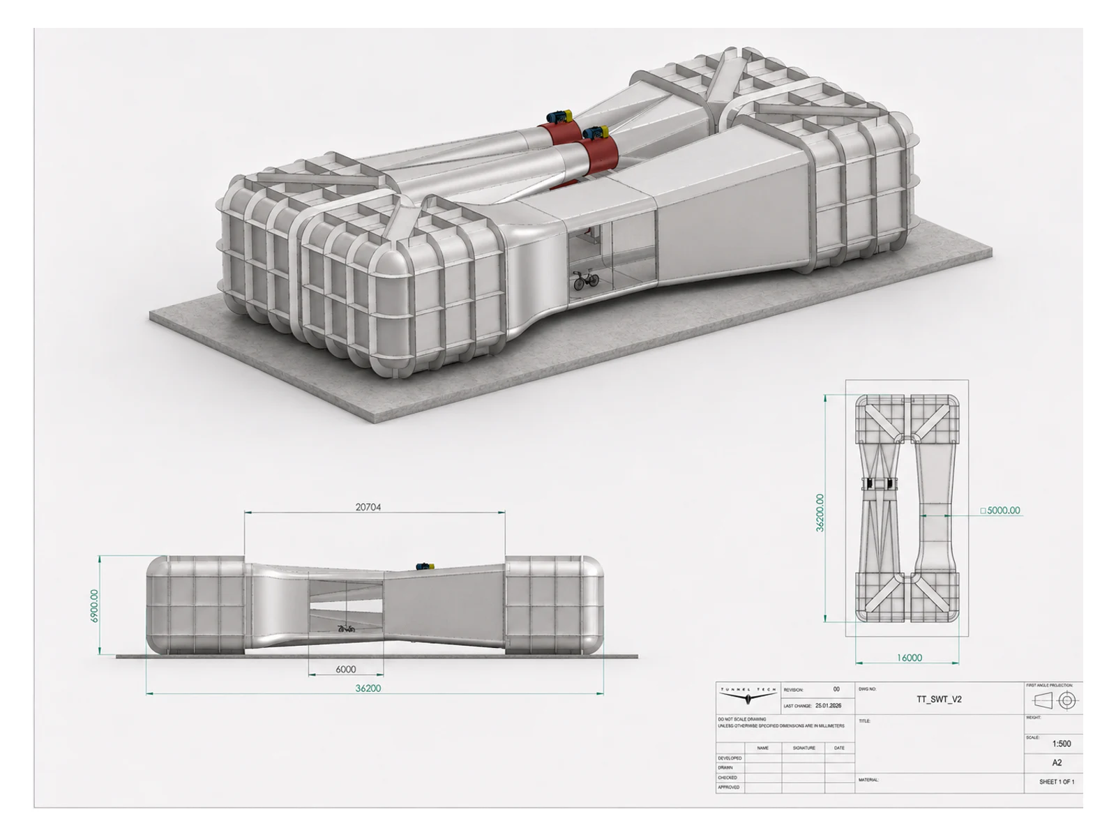
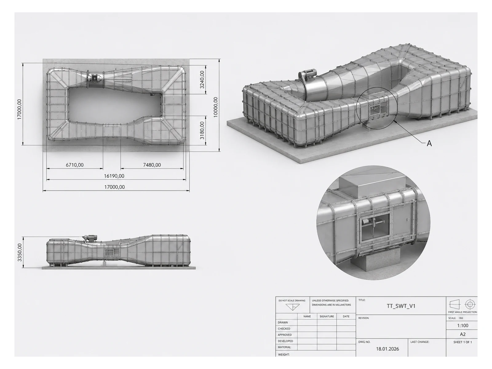
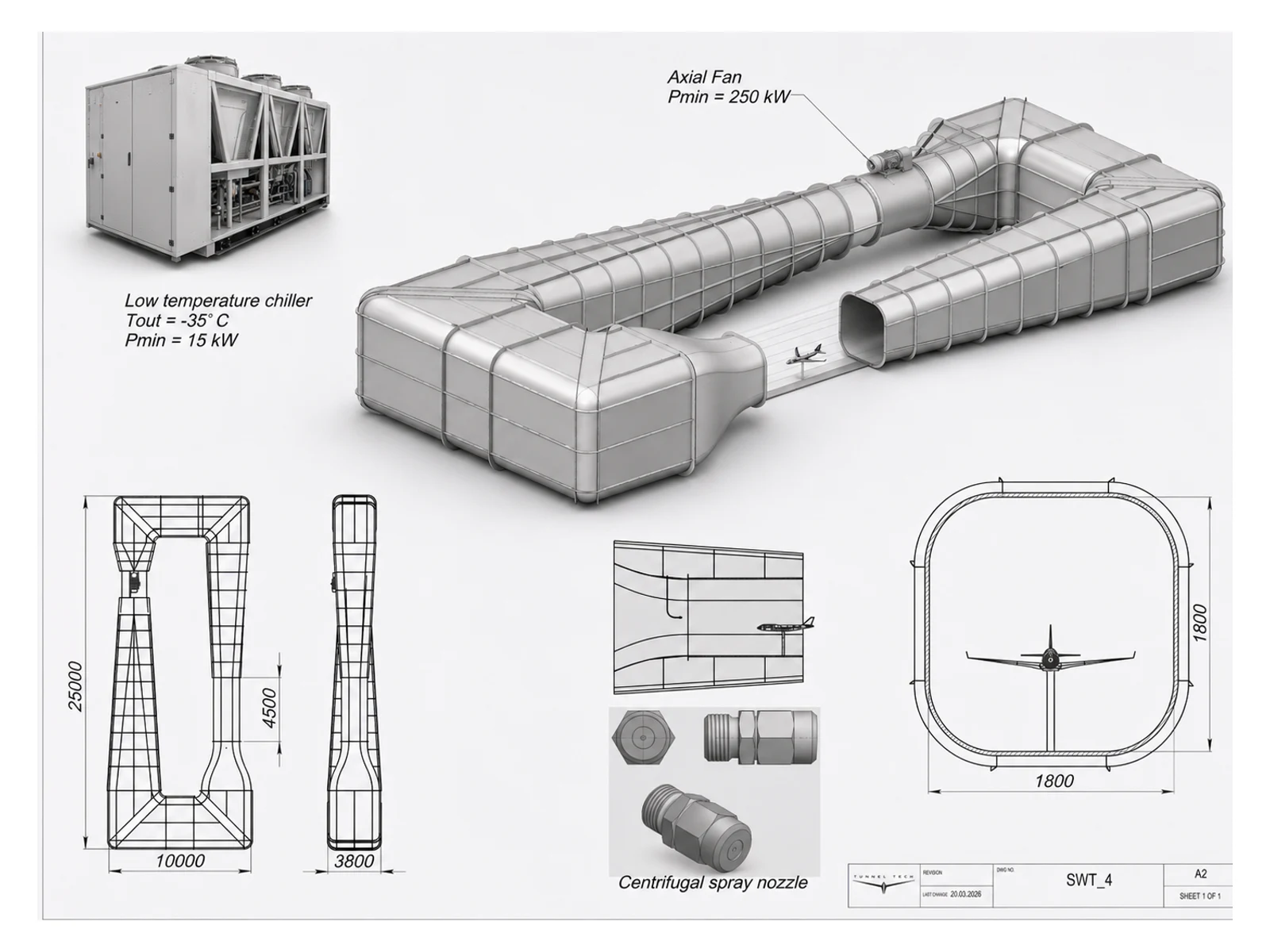
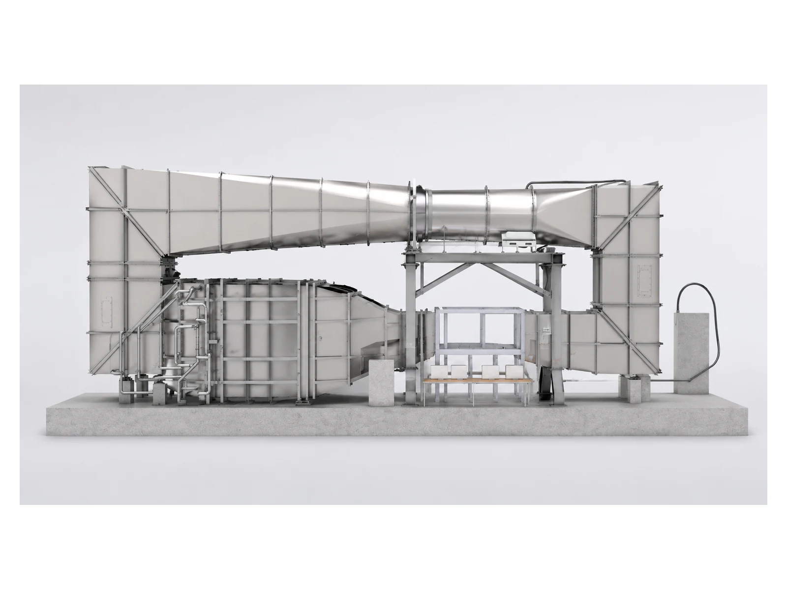
Examples of wind-tunnel configurations developed for different research objectives.
Compact research configurationFor components, propulsion assemblies and small complete UAVs where precise access and repeatability matter more than building a large circuit.
Larger full-aircraft configurationFor full-aircraft development, rotor interaction studies and scaled models that require more clearance, lower blockage and expanded instrumentation.
Climate-capable configurationA horizontal circuit with integrated cooling and media-delivery systems for programme-specific environmental test conditions.
Vertical-return configurationA vertically arranged return circuit reduces horizontal footprint where floor area is limited, trading footprint for available building height.
Concept designs only. Dimensions shown in the drawings illustrate preliminary layouts and do not define catalogue models. Final geometry, flow performance and system architecture are established during project engineering.
Built around the test matrix
The facility starts with what you need to measure
The circuit may be open or closed, compact or building-scale. What remains constant is the engineering sequence: define the test object, establish the flow envelope, control interference and integrate the measurement chain.
Geometry, access, model support, optical access and blockage managed around the aircraft.
Facility integration
Drive power, acoustics, cooling, controls, safety systems and interfaces to the customer building.
TunnelTech + EVG Lufttechnik
Wind-tunnel engineering backed by industrial fan manufacturing
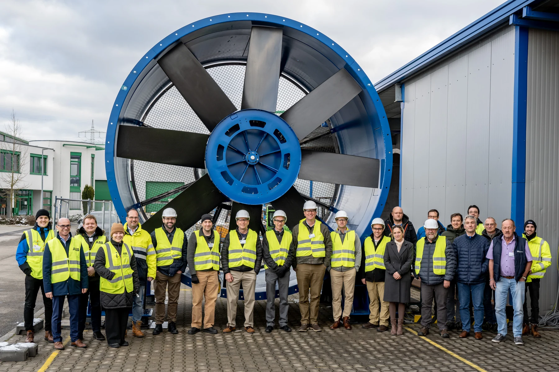
TunnelTech is a shareholder in EVG Lufttechnik GmbH, our long-standing strategic partner. EVG has worked in industrial fan engineering since 1977 and has manufactured axial fans since 1987.
This shared engineering and manufacturing base gives each project direct access to fan selection, ducting, flow conditioning, acoustics, controls and high-duty industrial operation.
Since 1977Industrial fan engineering
Since 1987Axial fan manufacturing
StuttgartEngineering and production
High-speed interceptor UAV testing
Powered testing for interceptor UAVs approaching 500 km/h
Fast interceptor platforms are emerging as a key counter-UAS response. At these speeds, propulsion, cooling, structural loads and control authority stop behaving as separate problems and have to be evaluated as one coupled system, under power, in the test section.
Test envelope up to
500km/h
Propulsion under aerodynamic loading, measured with the powerplant running
Stability and control authority across the mission envelope
Intake, motor and thermal behaviour at sustained high speed
Environmental options
Clean airflow is only the starting point
Where the programme requires it, environmental systems can be engineered into the circuit from the beginning. The final combination depends on the test matrix, temperature range, media handling and measurement requirements.
Wind profilesSteady flow, gusts, crosswind, shear and turbulence.Water exposureRain, spray and programme-specific water delivery.Sand and dustParticle-laden flow with recovery and filtration engineered for the media.Cold and icingTemperature control and calibrated spray conditions where required.Thermal conditioningHot and cold operating ranges for propulsion, batteries and electronics.Combined loadsProject-specific combinations developed as an integrated facility function.
Measurement integration
Instrumentation follows the question, not a standard package
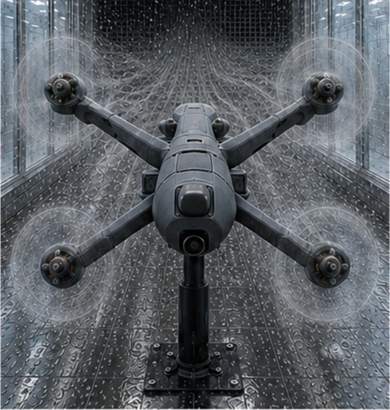
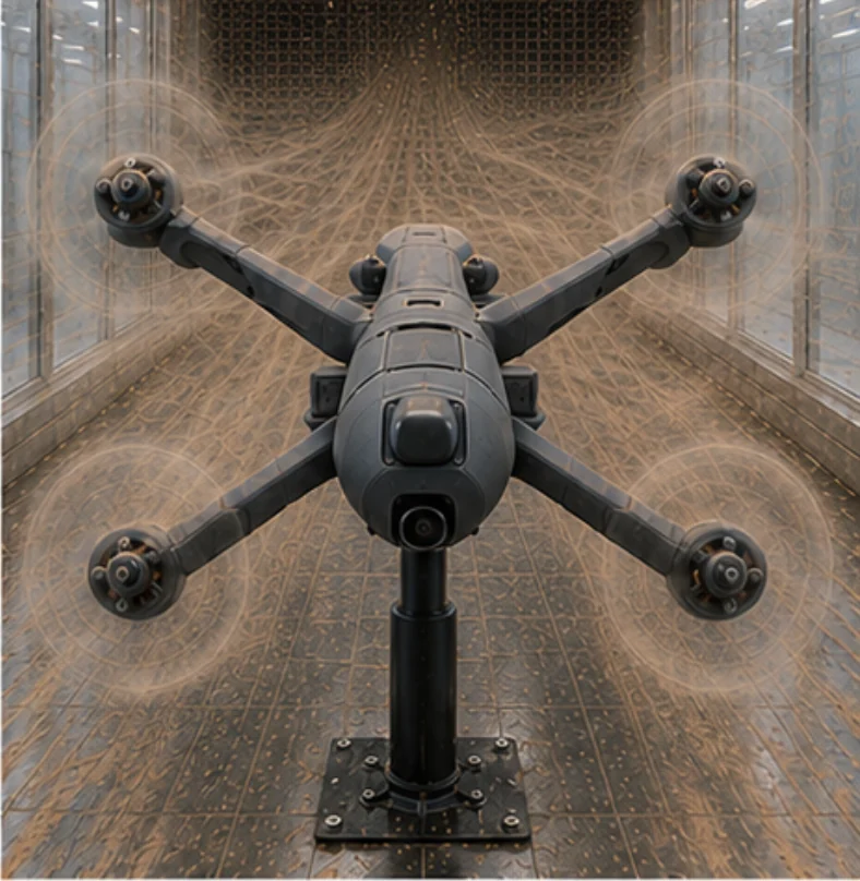
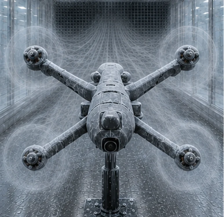
Depending on the programme, the facility can accommodate multi-axis force balances, pressure measurement, flow visualization, high-speed imaging, PIV, rotating model supports and customer-specific data acquisition.
Equipment, suppliers, accuracy targets and interfaces are defined during project engineering and integrated into the test section as one measurement chain.
Instrumentation described here represents available integration options. Final equipment is selected for each project.
Flow visualization / profile view
Real manufacturing. Real project sites.
New UAV applications. Proven engineering and manufacturing.
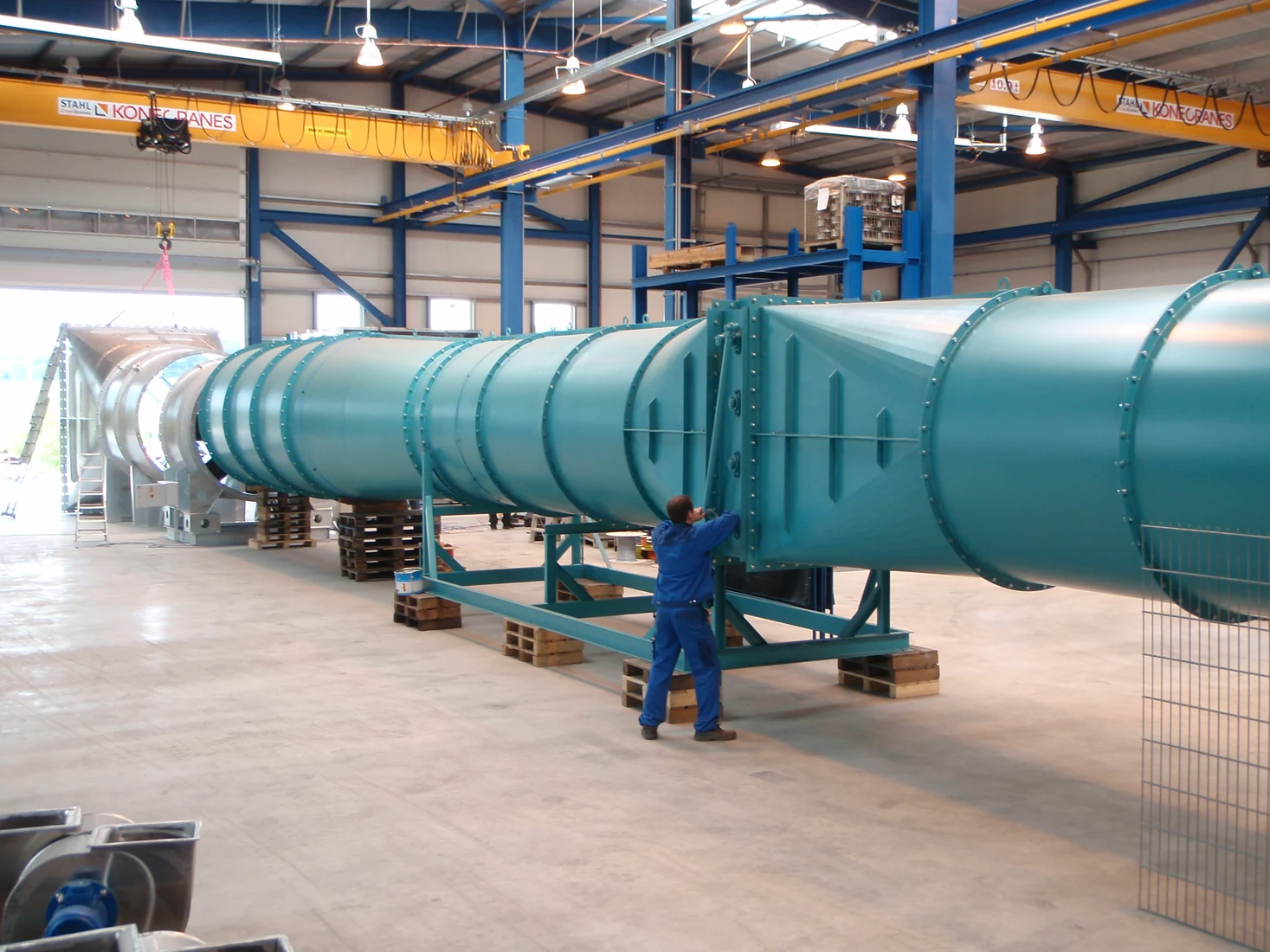
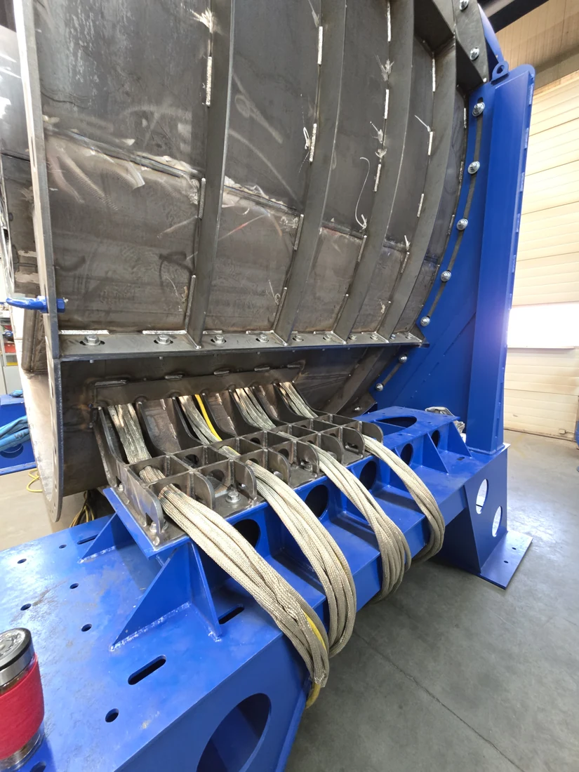
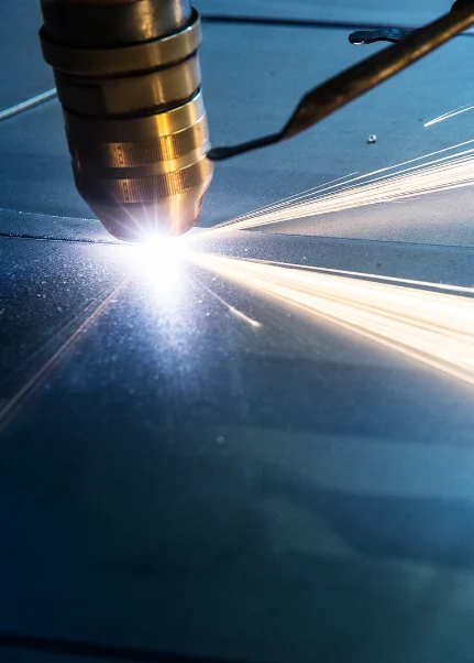
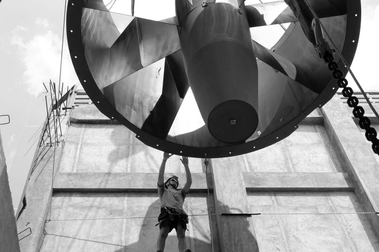
Actual manufacturing work in Stuttgart and installation work from wind-tunnel projects delivered around the world by TunnelTech.
Large-scale duct manufacturing at EVGHeavy-duty component fabricationLaser cutting of tunnel structural components, StuttgartInstallation work at an international project siteInstalled fan systems in a TunnelTech project
Single-point project responsibility
From test requirement to an operational facility
1
Needs analysis
Test objects, measurements, flow range and site constraints.
2
Aerodynamic concept
Circuit architecture, test section and fan-system demand.
3
Mechanical engineering
Structure, acoustics, climate systems, controls and safety.
4
Manufacturing and integration
Fabrication, factory assembly and interface integration.
5
Installation and commissioning
Site assembly, start-up, measurement and acceptance.
6
Training and lifecycle support
Operator training, service, spare parts and future upgrades.
Single-point responsibility, clear interfaces and long-term support.