
Introduction to Turning Vanes
In airflow management, the design of duct corners plays a key role in the efficiency and performance of ventilation and HVAC systems and wind tunnels. When air is forced through a sharp turn, as is often unavoidable in ductwork, it meets increased hydraulic resistance, which leads to higher pressure losses and turbulence. This not only reduces system efficiency, since more energy is needed to maintain the airflow, but also affects the structural integrity of the ductwork through the uneven pressure loads exerted by turbulent flow.
This is where turning vanes, also known as corner vanes or guide vanes, come in (Fig. 1). Installed inside the corner, turning vanes guide the air through the turn with minimal resistance, reducing pressure losses and turbulence without the additional space that a smooth radius bend requires. This makes turning vanes an ideal solution for managing airflow efficiently in a compact space.
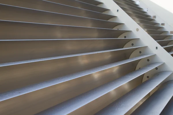
Fig. 1. TunnelTech turning-vane corner section assembly
High-performance turning-vane sections as an alternative to generic HVAC solutions.
The traditional way to reduce the turbulence, pressure loss and noise of a sharply curved duct is a radius elbow (Fig. 2 and Fig. 4, case 2). While radius elbows do partly mitigate the turbulence, noise and pressure losses typical of a sharp bend (see Fig. 4, case 1), they bring problems of their own.
Several conventional HVAC duct bends, made of smoothly curved sheet metal with bent splitter vanes, are shown in Fig. 2 on the left. These are typical standard variants commonly used in HVAC ductwork, e.g. compliant with the DW144 ductwork standard.
Such duct components are common and cost-effective for small applications in civil engineering, small businesses and low-power HVAC systems where energy cost is not a significant factor. However, this design is not a good solution for ventilation and cooling systems in medium- and large-scale, high-capacity applications – power generation, metallurgy, turbomachinery, heat exchangers, waste heat recovery and modern green and renewable energy – where hydraulic efficiency and energy savings are a must.
However, there is no need to build a custom, non-standard duct every time the energy consumption of a hydraulic network needs to be fully optimized. The same Figure 2, on the right, shows a variant of TunnelTech's diagonal turning-vane corner section, which is energy-efficient, low-noise and low-turbulence, meets industry standards for HVAC systems, and can also be used in large-scale, high-power industrial applications. An example of a large-scale facility into which the diagonal turning-vane section can easily be integrated is shown in Fig. 3.
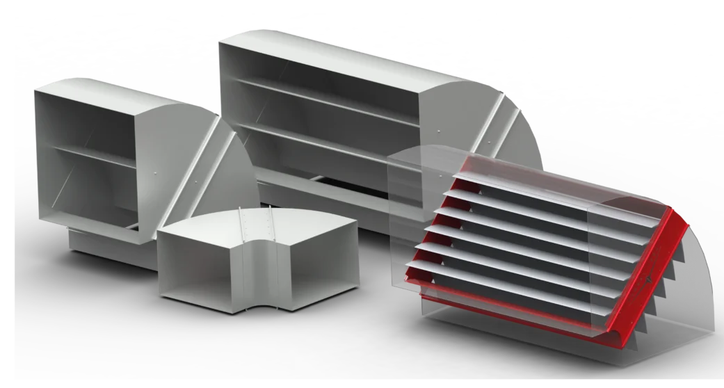
Fig. 2. Conventional medium-scale HVAC smooth elbow with a sheet-metal splitter vane to the DW144 standard (left), and a high-performance TunnelTech diagonal turning-vane assembly for standard air ducts (right).
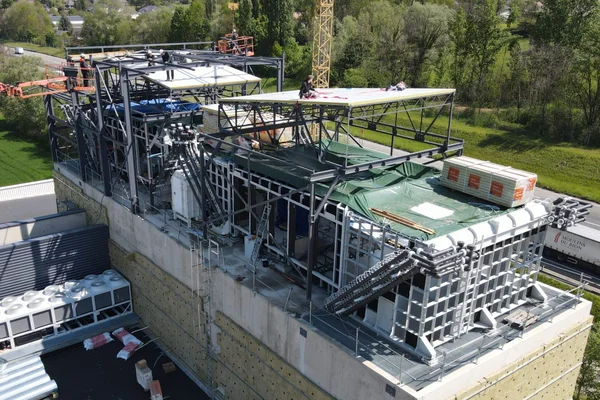
Fig. 3. Large-scale TunnelTech air-duct turning-vane corner sections for wind tunnels, power generation and industrial applications.
Turning-Vane Design for Reducing Pressure Drop, Turbulence and Noise
To compare different turning-corner designs, the pressure drops (ΔP) and CFD-simulated flow patterns are given in Fig. 4 below. An inlet airflow velocity of 20 m/s and a 2×2 m square duct were chosen as a demonstration example. The 20 m/s speed was chosen because professional-grade vertical wind tunnels for indoor skydiving normally operate most of the time in modes where the flow velocity in the turning section is between 10 and 30 m/s. CFD calculations were performed at 1 standard atmosphere, 20 °C and zero air humidity with a compressible gas and an adiabatic wall with a roughness of 250 µm. A mesh of 6 to 10 million cells per domain was used. A flat inlet profile and 2% turbulence were applied at the inlet boundary. Turbulence was modeled using the k-ε model.
Note: The illustrations in Fig. 4 are specific examples, presented solely to illustrate the operating principles and to compare a few types of turning-vane corner sections. They cannot be taken as general results for every use case. For each real ventilation system or other hydraulic network, the specific hydraulic parameters, duct size and shape, roughness and structural irregularities, flow non-uniformities and exact physical gas properties must be taken into account at every computational point. You can order such a calculation for a specific system by contacting us.
The following design cases are shown:
- Corner section without turning vanes.
- Smoothly curved corner section (r = ½ of the duct height) with radially bent splitter vanes. The pressure drop also depends on the number and geometry of the splitters. The example shows a minimum number of optimally shaped splitter plates.
- Simple radially curved thin plates (10–20 mm thick).
- Typical unoptimized turning vanes from our closest competitors.
- TunnelTech turning vanes (TTE-TV) with an optimized profile.
The most significant problem with curved ducts that have a small number of simple bent-plate splitters (or no vanes at all) is the pressure and velocity distribution at the exit of the turning section (Fig. 4, case 2, see the outlet cross-section). The velocity increases from the outer wall to the inner wall of each flow sub-channel, producing non-uniform flow, severe turbulence and noise. The smaller the turn radius, the greater the risk of flow separation, distortion of the pressure and velocity fields, higher noise and higher pressure drop.
The only way to overcome these issues is a large curvature radius for the corner section and a larger number of splitter vanes. This creates a second problem – the extra space needed to accommodate such bends and the material cost of several curved splitters sized to the duct cross-section. In large duct systems, smooth radius bends can lead to unreasonably large structures, making this approach impractical in many cases, especially where space is at a premium. The additional space needed is shown by the dashed lines in Fig. 4, case 2 below. The height and width of each turn must be increased by at least ½ of the duct size. For recirculating wind tunnels this means increasing the building dimensions by several meters in each direction, which drives up ductwork costs and capital investment. In addition, each splitter costs as much as the duct wall itself.
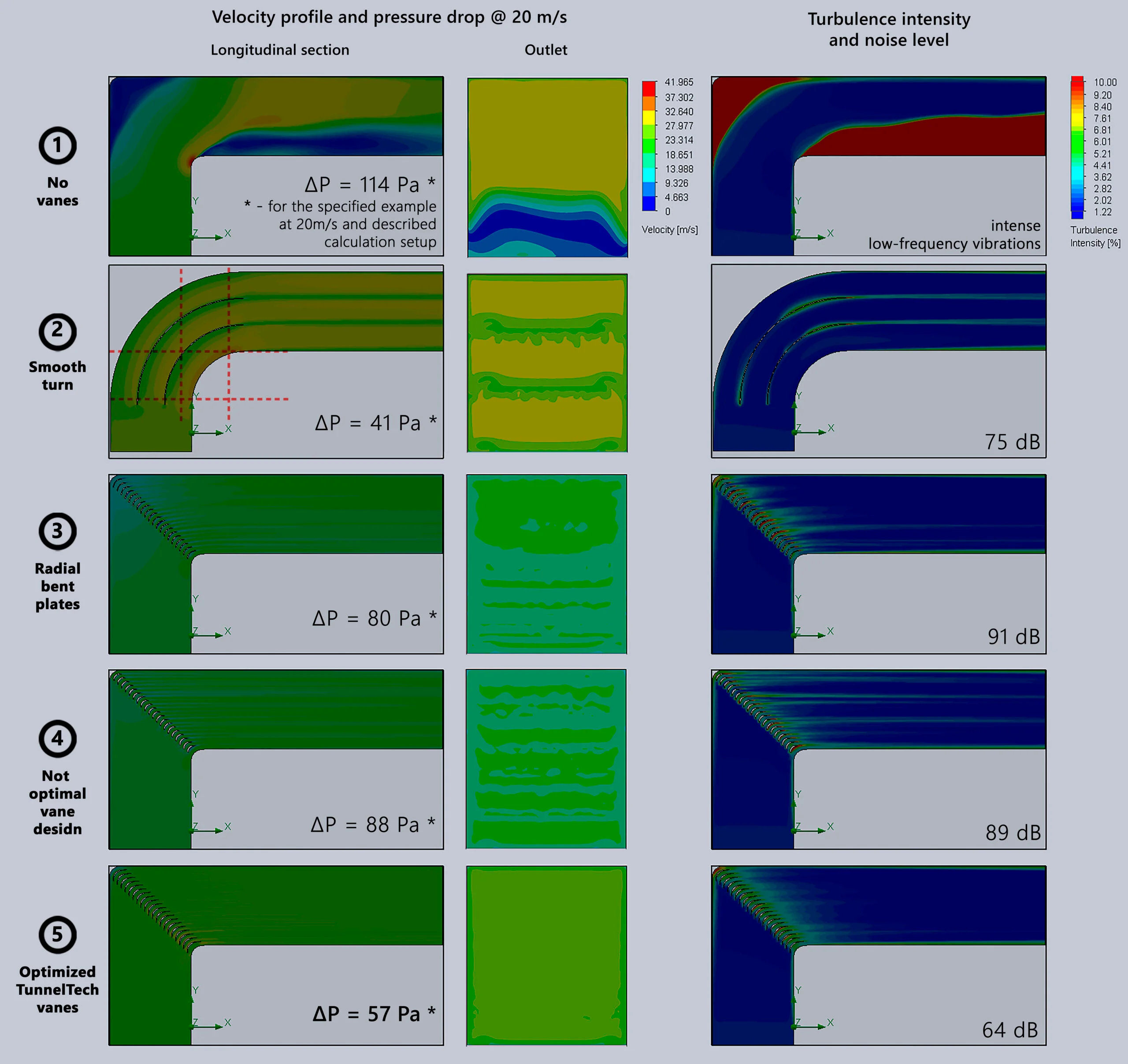
Fig. 4. Corner sections in ductwork – design and performance comparison
The optimal solution for wind tunnels and industrial ventilation is a diagonal cascade of airfoil-profile turning vanes, as shown in Figure 4, cases 3–5.
All CFD images above are for an air-duct corner section with a 2×2 m inlet at 20 m/s airflow velocity, as an example – the case most relevant to indoor skydiving and low-speed subsonic wind tunnels.
Figure 4, case 3 shows a corner section with simple vanes made of thin bent sheet metal. Fig. 4, case 4 shows the best turning vanes offered by TunnelTech's closest competitors. Both have a shorter chord and an unoptimized airfoil shape, resulting in what appears to be residual flow non-uniformity at the section exit, higher aerodynamic resistance and more duct noise. Thin vanes made of simple bent sheet metal usually exceed permissible noise levels even at low airspeed, and a thick, short profile with a low chord-to-thickness ratio also has a smaller surface area, which is a drawback where cooled turning vanes are used for heat transfer.
The lower part of Figure 4, case 5 shows an air-duct corner fitted with high-performance TunnelTech turning vanes (to order, refer to part number TTE-TV-90). As the cross-sections show, the flow is more uniform with properly profiled vanes, which means lower pressure drop and low turbulence.
The outlet pressure/velocity profile is also much better for TunnelTech corner sections fitted with long-chord vanes than in the other cases. The result is TunnelTech's unrivaled aerodynamic quality, as reflected in numerous reviews by professional skydivers and other customers.
All of the above data, including chord length and cooling options, is also summarized in Table 1.
| Case / Vane type | ΔP (Pa) (*) | ξ (*) | Chord length (mm) | Cooling |
|---|---|---|---|---|
| 1. No vanes, sharp turn | 114 | 0.47 | — | No |
| 2. Smoothly curved corner section | 41 | 0.17 | > 2000 | No |
| 3. Simple radially curved thin plates | 80 | 0.33 | 250–500 | No |
| 4. Closest competitors' turning vanes | 88 | 0.37 | 280 | Yes |
| 5. TunnelTech optimized turning vanes | 57 | 0.24 | 500 | Yes |
The hydraulic loss coefficient for the duct turning section with TunnelTech and competitors' vanes over the speed range up to 100 m/s, calculated for the same geometry and initial conditions, is given in Fig. 5.
More details on hydraulic losses along the duct length, local resistance and the total hydraulic loss coefficient are given below.
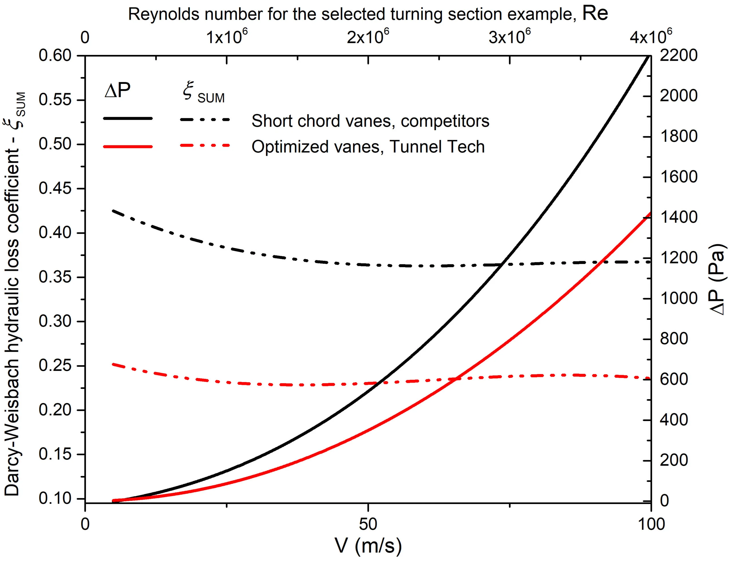
Fig. 5. Comparison of TunnelTech and competitor turning sections: Darcy–Weisbach hydraulic loss coefficient for the same geometry and initial calculation conditions.
Mitigating Turbulence for Reliable Hydraulic and Structural Safety Calculations
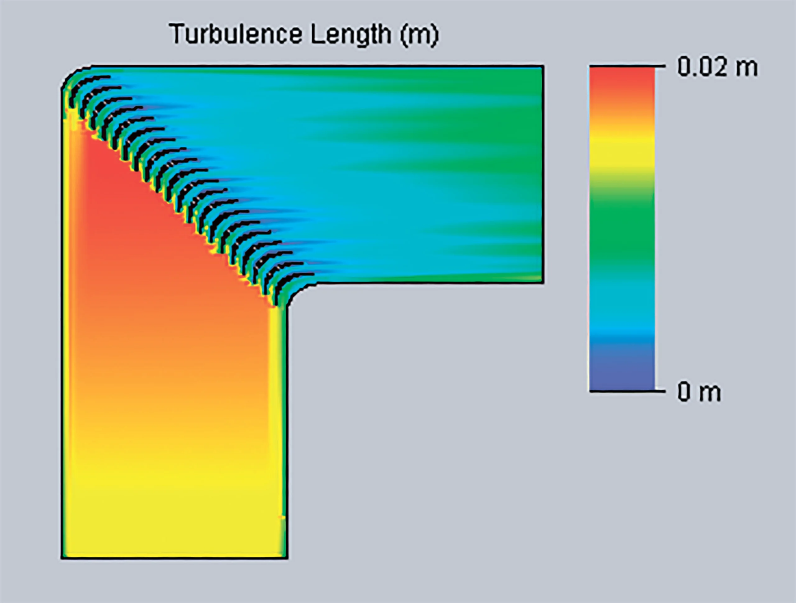
Fig. 6. TunnelTech turning-vane corner section: turbulence scale (m) at 20 m/s
A smooth, predictable pressure/velocity profile is especially important in applications where high turbulence or flow separation is unacceptable, such as experimental wind tunnels, indoor skydiving facilities and high-power installations. These parasitic effects, together with the pressure pulsations caused by flow separation and large-scale turbulence, are also unacceptable in installations that must be free of acoustically induced vibration and where no static pressure deviations are allowed for reasons of air-duct structural stability. In addition, turbulent flow is a common source of noise, further degrading overall system performance and end-user comfort.
It should also be borne in mind that flow irregularities tend to grow and intensify downstream unless flow straighteners, honeycombs, turbulence screens or other flow-conditioning devices are used [1-3]. Accurate gas-dynamic analysis requires calculating the resistance of each successive duct element with the real inlet pressure/velocity profile generated by the previous element of the hydraulic network. For long hydraulic networks it is often impossible to run a CFD simulation of the entire system because of its sheer size. In such cases, approximate semi-empirical calculations based on dimensionless flow numbers and geometric criteria [4], or software based on such methods, are used. Likewise, FEA modeling of duct structural stability is typically performed with a steady static pressure field applied to the duct walls. Severe flow irregularities developing downstream can therefore also introduce error into safety-critical analyses of load-bearing structures.
Approximate methods usually do not deal with distortion of the velocity profile at the inlet of a hydraulic network element; at best they account for whether the profile is fully developed or not yet developed (uniform), and for the boundary-layer parameters. In wind tunnels and industrial ventilation systems, each turn of the flow can cause non-uniformity and strong swirl, which introduces uncertainty into hydraulic resistance calculations for long networks. Wherever possible, therefore, large velocity-profile irregularities should be avoided.
Fig. 6 and the results above show that turning sections with TunnelTech turning vanes not only create no additional flow disturbance but can also be used to damp swirl and non-uniformity downstream of the section. A turning-vane corner section with TunnelTech vanes can therefore also act as an effective flow straightener when installed downstream of an axial fan, duct diffuser, heat exchanger, test section, duct branch or tap-off, or any other turbulence-generating element.
Local Resistance Coefficient
The local resistance of a turning corner can be calculated using the well-known Darcy–Weisbach equation:
ΔP = ξ · ρ · v² / 2
Where:
- ΔP – total pressure loss (pressure drop) in Pa;
- ξ – local resistance (Darcy–Weisbach) coefficient;
- ρ – fluid density (kg/m³);
- V – fluid velocity at the inlet cross-section (m/s).
These parameters, which determine the energy efficiency of the air duct, depend strongly on the turning-vane design.
According to [4], the total resistance of a complex hydraulic element can be represented as the sum of the frictional resistance along its length ξL and the local resistance ξ0:
ξSUM = ξL + ξ0
For a straight air duct the length resistance is proportional to the length and inversely proportional to the hydraulic diameter, as expressed by the formula:
ξL = (L / D) · f
where f is the Darcy friction factor.
For simply shaped ducts (e.g. circular, square, hexagonal), f can be expressed as a nonlinear function of the Reynolds number alone – see Chapter 2 in [4] or https://en.wikipedia.org/wiki/Darcy–Weisbach_equation
The friction factor f for a simple round pipe (circular duct) with smooth walls, a fully developed flow profile at the inlet and a turbulent regime (Reynolds numbers Re > 4×10³) can be calculated from the formula:
f = 1 / (1.81 · lg(Re) – 1.64)²
For real ducts, wall roughness must also be taken into account.
Fig. 7 below shows a plot of the Darcy friction factor versus Reynolds number Re for various relative wall roughness values, first published by Nikuradse in [5-8]. This graph is also known as the Moody diagram [9] or the Colebrook–White correlation [10-11]. A more recent study of smooth pipes can be found in [12].
The diagram shows the complex dependence f(Re) for a round pipe with different roughness values. For square and other non-circular ducts the diagram is more complicated still. The flow regime (Reynolds number), duct shape and relative wall roughness must therefore all be taken into account.
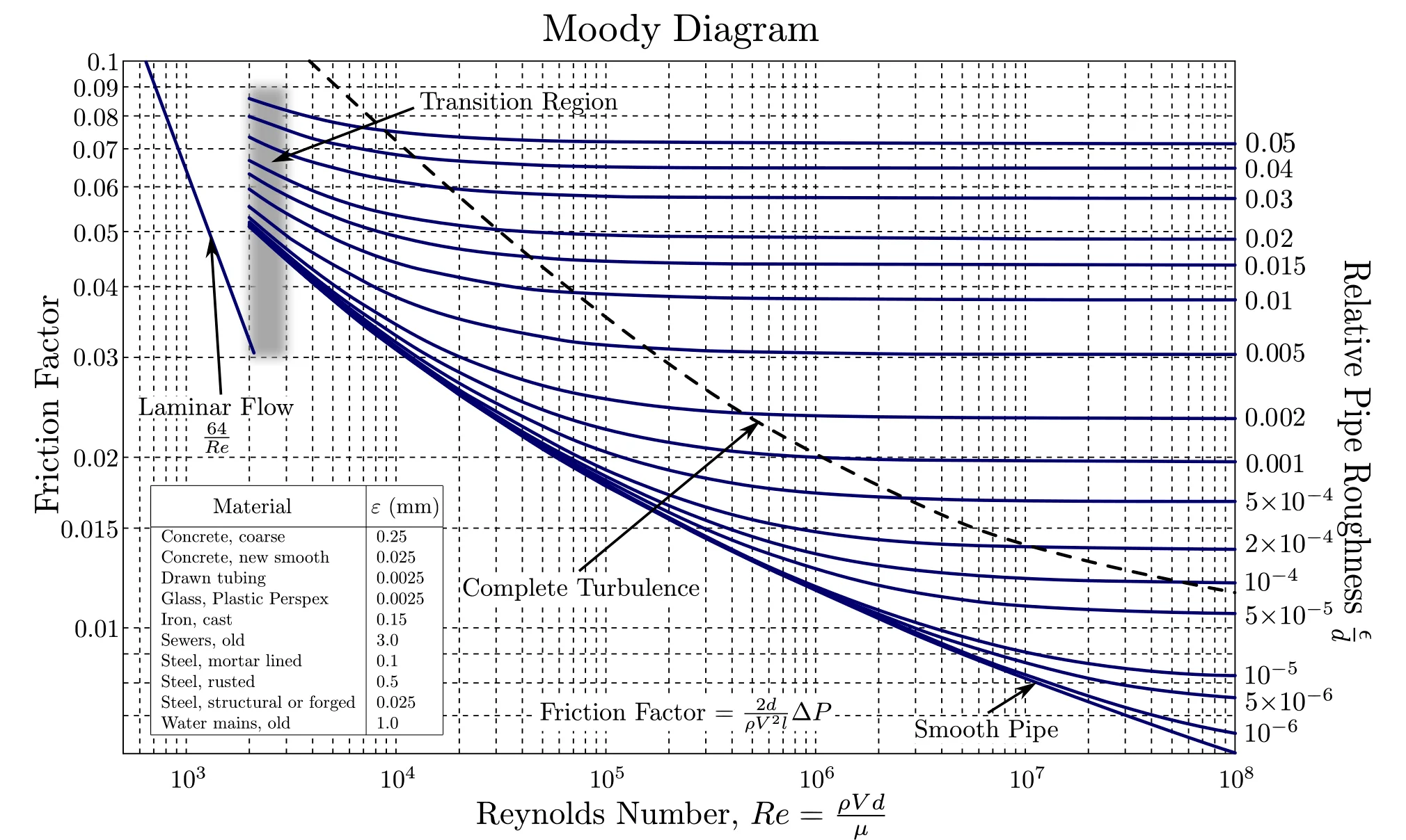
Fig. 7. Moody (a.k.a. Nikuradse) diagram showing the Darcy–Weisbach friction factor fD plotted against Reynolds number Re for various relative roughness values – Original diagram: S. Beck and R. Collins, University of Sheffield, shared under CC BY-SA 4.0, wikimedia.org
For real, rough ducts it is still possible to represent the total resistance as the sum ξSUM = ξL + ξ0 of the length resistance and the local resistance.
Splitting the resistance into this sum simplifies the study of duct parameters, since the local resistance ξ0 can be calculated for a simplified element geometry – for example, with a periodic formulation of the problem on a smaller computational domain, or in a 2D formulation. Note the size of the computational domain in the examples shown in Fig. 4 – the section is 3 m high and 18 m long, and adequate grid convergence only begins above 10 million mesh elements. A periodic or 2D formulation of the same cases could use an order of magnitude fewer mesh elements, and the simplified calculation of each velocity point on the ΔP(v) curve would take minutes or even seconds rather than hours.
Splitting the resistance into two components can therefore greatly simplify calculations – the local resistance ξ0 is determined quickly, and the length resistance ξL is then added. The latter can be estimated quickly from published tables or by approximate formulas based on dimensionless numbers and duct geometry parameters. For hydraulic and duct-network elements with abrupt changes in flow direction (angled elbows, smooth bends, bends of various angles with and without turning vanes), a similar approach and method are presented in Chapters 6-1 and 6-2 of the comprehensive Handbook of Hydraulic Resistance [4].
Technical Specifications
Comprehensive technical data for precise engineering and performance calculations.
Integrated Cooling Technology
Revolutionizing tunnel design, our turning vanes feature integrated internal coolant channels—delivering superior heat exchange efficiency without compromising airflow quality.
- Massive heat dissipation capacity, scalable from hundreds of kilowatts to tens of megawatts.
- Efficient thermal management with zero adverse impact on airflow turbulence or stream quality.
- Engineered with six integrated internal cooling channels per vane for maximum thermal efficiency
- Seamless integration with standard industrial water cooling infrastructures
Product Highlights
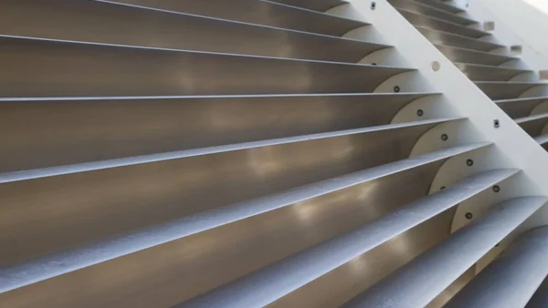
TunnelTech's airflow turning vanes (product TTE-TV) are at the forefront of this technology, offering unparalleled efficiency in airflow management. Our products are designed for a wide range of applications, from indoor skydiving facilities and wind tunnels to HVAC and ventilation systems, and embody the cutting edge of aerodynamic design and energy efficiency.
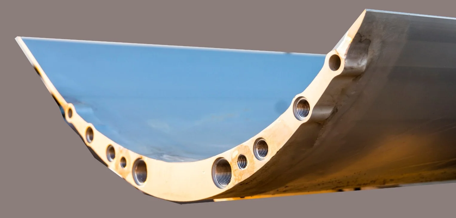
Turning-Vane Section Performance in Air Ducts
TunnelTech's high-performance turning vanes set the industry standard for power and aerodynamic efficiency. Our energy-saving turning vanes are engineered to minimize aerodynamic losses, ensuring smooth airflow and reducing energy consumption.
TunnelTech turning vanes have excellent local resistance characteristics in air ducts. The resistance parameters, calculated with the Darcy–Weisbach equation as described above, are presented in the figures below (see Fig. 8) and in the Turning Vane Datasheet.
In general, where the duct size is unknown, values are given for an idealized element with periodic lateral boundary conditions, without accounting for the additional wall friction along the length, roughness or other local parameters. Fig. 8 gives the values for an idealized corner element with TunnelTech vanes, calculated for a stack of 15 vanes with periodic boundary conditions as an approximation of an infinite periodic cascade.
Fig. 8. TunnelTech turning vane: local resistance coefficient and corresponding pressure drop.
If the HVAC or other hydraulic system consists of ducts whose flow cross-section does not generally change along the flow path, it is convenient for approximate calculations to estimate the resistance per unit length (which must, of course, be estimated over the entire velocity range):
KL = ξL / L = f / Dh
where Dh is the hydraulic diameter of the duct. The value of KL is easy to determine from reference books, as discussed above. Multiplying it by the length and adding the local resistance values ξ0 taken from datasheets or calculated independently gives a quick estimate of the total pressure loss in the system.
ξSUM = KL · L + ξ0
The illustrative examples in Fig. 4 – a 2×2 m square duct with the gas parameters and roughness used in the calculation – have a resistance per unit length of the order of KL = ξL / L ~ 2.1 Pa. This value applies to a plain square duct without bends, vanes or other internal equipment. Over the full 21 m that the air travels along the duct, this gives a pressure drop of ~44 Pa. Adding the value from Fig. 8 (11 Pa at 20 m/s, taken from the Turning Vane Datasheet, Table A.2.1) gives a total resistance of 55 Pa for a real 2×2 m duct section with turning vanes. This value is in good agreement with the value shown in Fig. 4, case 5.
More information on approximate methods for calculating the resistance of ducts of any shape without CFD can be found in [4] and similar literature.
Note: The examples in Fig. 4 are only a special case demonstrating how the turning vanes work and cannot be used to evaluate an arbitrary duct. Figure 8 applies more broadly, but the specific parameters of the client's duct still have to be considered. Each system needs a detailed analysis, which you can order from TunnelTech. For an accurate calculation of duct hydraulic resistance and an expert assessment of the energy consumption of your ventilation or wind tunnel equipment, please contact us.
Additional information about our services and R&D can be found on the Technology page and in the Services section.
Turning Vanes for Industrial Cooling and Heating
Unique among turning vanes for industrial air ducts, our products can circulate coolant at a high flow rate, allowing the air to be cooled or heated efficiently as it passes through the duct. This opens up new possibilities in thermal regulation – indoor climate-control vanes and low-resistance in-duct heat exchangers – giving our clients versatile solutions for their airflow needs.
Rated using the HTCL (heat transfer coefficient per linear meter) method, which quantifies the heat flux (in watts) per meter of turning-vane length per kelvin of logarithmic mean temperature difference (ΔTLMTD) between the external air and the vane coolant, our turning vanes are engineered for effective heat transfer across a range of airflow conditions, guaranteeing stable performance and temperature regulation.
Heat transfer coefficient parameters for the water-cooled turning vanes are presented in Fig. 9 for both dry and moist air, where ΔP [kPa] is the water pressure difference between the inlet and outlet vane ports (blue and red in Fig. 10).
Fig. 10. Turning-vane cooling channels
Fig. 9. HTCL coefficient. Dry (RH = 0%) and moist air (RH = 90% at 30 °C) at different coolant (water) pressure differences between the inlet and outlet coolant channel ports.
Turning Vanes for Waste Heat Recovery
Cooled turning vanes with integrated heat-exchange channels offer a versatile solution for waste heat recovery across a variety of applications. Integrated into heat-exchange systems, these vanes can capture excess thermal energy that would otherwise be lost and transfer it to heat recovery systems, significantly improving overall system efficiency.
In practice, this technology can be used in many areas. In industrial processes, for instance, cooled turning vanes can recover waste heat from exhaust gases and use it to preheat incoming fluids or air, reducing energy consumption. In HVAC systems, the same principle is applied in devices such as heat recovery ventilators (HRVs) and energy recovery ventilators (ERVs), which transfer heat between the exhaust and supply air streams. This minimizes the energy needed to heat or cool incoming air, leading to substantial energy savings.
Cooled turning vanes can also be integrated into power generation and renewable energy systems. In combined heat and power (CHP) plants, for example, waste heat from electricity generation is recovered and used for heating, improving the overall efficiency of the system. In geothermal energy systems, these vanes can help manage the thermal energy extracted from the ground, optimizing the heat transfer processes.
In green and renewable energy initiatives, waste heat recovery plays a critical role in reducing carbon footprints and improving the sustainability of energy systems. The approach is in line with lean manufacturing principles, improving resource efficiency and reducing operating costs through effective heat management. In ESG projects, moreover, adopting such technologies demonstrates a commitment to minimizing environmental impact and optimizing resource use, in line with broader sustainability goals.
Heat Recovery – Related Projects
TunnelTech has extensive experience in delivering heat-exchange and HVAC projects designed for waste heat recovery with cooled turning vanes. By integrating these vanes into heat-exchange systems engineered to capture and reuse thermal energy that would otherwise be lost, TunnelTech makes it possible to recover waste heat more effectively from a wide range of industrial and commercial processes. This not only improves energy efficiency but also supports sustainability goals by reducing energy consumption and operating costs.
Applications
Our turning vanes serve a wide range of industries and applications
HVAC Systems
| Commercial Buildings | Ductwork optimization; energy efficiency; lower operating costs; better health and safety through efficient control of air quality and temperature |
| Residential Complexes | Comfortable living environments with optimal air quality and airflow; better health and safety |
| Data Centers | Thermal-management turning vanes maintain the critical temperature and humidity levels needed for server performance and longevity |
Civil Engineering Ventilation Systems
| Hospitals and Healthcare Facilities | Quiet-running turning vanes provide the vital air-quality control that protects patients and staff; better health and safety through efficient control of air quality and temperature |
| Educational Institutions | Better learning environments through improved air circulation |
Environmental Control
| Electronics, Biotech, Foodtech and other High-tech Facilities / Clean Rooms | Temperature and humidity control for high-tech and demanding production; air-conditioning turning vanes maintain stringent airflow standards for manufacturing and research |
| Sporting Arenas | Comfort and safety for athletes and spectators alike |
Industrial and Specialized Applications
| Tunnel Construction and Maintenance | Better air quality and safety for workers in tunnel environments |
| Industrial Facilities | Ductwork optimization; energy efficiency; sustainable development; lower operating costs |
| Foundries and Heavy-Duty Facilities | Energy efficiency; lower operating costs; waste heat recovery; decarbonization and ESG; heavy-duty HVAC air ducts; thermal management |
| Marine Engineering | Improved ventilation on ships and submarines for crew comfort and equipment reliability |
| Mining and Underground Construction | Essential ventilation for mines and other underground structures, reducing the risk of hazardous conditions |
Each of these applications benefits significantly from the advanced design and functionality of TunnelTech's turning vanes, which mark a leap forward in efficient airflow management. By choosing TunnelTech's low-drag turning vanes, clients can expect not only to meet but to exceed their system performance goals, all while
- •reducing energy consumption* by up to 30%
- •reducing noise* by 60%, compared to conventional air ducts.
* Experimental results for the TT45 PRO wind tunnel geometry.
For inquiries and more details on how our turning vanes can be tailored to your specific needs, please contact our team. Let TunnelTech be your partner in achieving optimal airflow management.
Installation & Maintenance
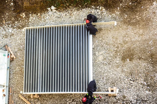
- •Dimensions and Specifications
Verify duct dimensions and turning vane specifications before installation
- •Mounting Options
Available in clamp-on, bolt-on, and weld-on configurations
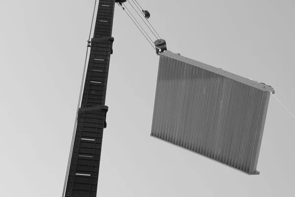
- •Load Handling
Follow load handling guidelines for safe transport and positioning
- •Step-by-Step Installation
Detailed installation instructions provided with each product delivery
- •Inspection Schedule
Regular visual inspections to ensure vane alignment and structural integrity
- •Cleaning Procedures
Periodic cleaning to remove dust and debris buildup on vane surfaces
- •Wear and Tear Monitoring
Monitor for signs of corrosion, erosion, or mechanical damage
- •Troubleshooting Guide
Address common issues such as vibration, noise, or reduced airflow efficiency
Documentation
Technical information on TunnelTech wind tunnel corner section assemblies and turning vane parameters is available in a comprehensive datasheet covering the TTE-TSA and TTE-TV products. The documentation includes design options, local resistances for horizontal and vertical 90-degree turning corners, and hydraulic and heat-transfer parameters for cooled turning vanes.
Download TTE-TSA Datasheet (PDF)References and Related Publications
Additional information on the design and optimization of turning vanes for wind tunnels, industrial ductwork, HVAC ducts and airflow management equipment, fan flow straighteners, etc. can be found at the links below:
- Baals, D.D., and W.R. Corliss. Wind Tunnels of NASA. NASA; SP-440. Scientific and Technical Information Branch, National Aeronautics and Space Administration, 1981. books.google.rs
- Barlow, J.B., W.H. Rae, and A. Pope. Low-Speed Wind Tunnel Testing. Wiley, 1999. books.google.rs
- Pope, A., and K.L. Goin. High Speed Wind Tunnel Testing. Wiley, 1965. books.google.rs
- Idelchik, I. E. “Handbook of Hydraulic Resistance, Revised and Augmented.” Begell House, 2008. begellhouse.com
- Nikuradse, J. 1933. Strömungsgesetz in rauhen Rohren, VDI Forschungshefte 361. (English translation: Laws of flow in rough pipes). Technical report, NACA Technical Memorandum 1292. National Advisory Commission for Aeronautics (1950), Washington, DC. ntrs.nasa.gov
- Nikuradse, J. (1931), Strömungswiderstand in rauhen Rohren. Z. angew. Math. Mech., 11: 409-411. doi.org/10.1002/zamm.19310110603
- Nikuradse, J. 1932. Laws of turbulent flow in smooth pipes (English translation). NASA TT F-10: 359 (1966).
- Nikuradse, J. 1930. Widerstandsgesetz und Geschwindigkeitsverteilung von turbulenten Wasserströmung in glatten und rauhen Rohren, Proc. 3rd Int. Cong. Appl. Mech., Stockholm, 239-248.
- Moody, L. F. 1944. Friction factors for pipe flow. Trans. ASME, 66, 671–684. doi.org/10.1115/1.4018140
- Colebrook, C. (1939). Turbulent Flow in Pipes, with Particular Reference to the Transition Region between the Smooth and Rough Pipe Laws. Journal of the Institution of Civil Engineers, Volume 11 Issue 4, February 1939, pp. 133-156. doi.org/10.1680/ijoti.1939.13150
- Colebrook, C. F. (February 1939). “Turbulent flow in pipes, with particular reference to the transition region between smooth and rough pipe laws”. Journal of the Institution of Civil Engineers. London. Volume 12 Issue 8, October 1939, pp. 393-422. doi:10.1680/ijoti.1939.14509.
- McKeon, Beverley J., Chris J. Swanson, Mark V. Zagarola, Russell James Donnelly, and Alexander J. Smits. “Friction Factors for Smooth Pipe Flow.” Journal of Fluid Mechanics 511 (2004): 41–44. doi.org/10.1017/S0022112004009796
- Mehta R.D., Bradshaw P. Design rules for small low speed wind tunnels. The Aeronautical Journal. 1979;83(827):443-453. doi.org/10.1017/S0001924000031985
- Cattafesta, Louis, Chris Bahr, and Jose Mathew. “Fundamentals of Wind-Tunnel Design.” In Encyclopedia of Aerospace Engineering. John Wiley & Sons, Ltd, 2010. doi.org/10.1002/9780470686652.eae532
- Hurtado, J.P.; Villegas, B.; Pérez, S.; Acuña, E. Optimization Study of Guide Vanes for the Intake Fan-Duct Connection Using CFD. Processes 2021, 9, 1555. doi.org/10.3390/pr9091555 mdpi.com
- Gelder, T.F., Moore, R.D., Sanz, J.M. and McFarland, E.R. Wind tunnel turning vanes of modern design. 24th Aerospace Science Meeting. NASA Technical Memorandum, AIAA Paper 86-0044. Reno, Nevada, January 1986. semanticscholar.org
- Schirf, Collin. “Optimization of Expanding Turning Vanes by Bezier Curve Parameterization,” Master Dissertation, University of Maryland, 2019. doi.org/10.13016/5x1x-gxhz
- Almeida, Odenir De, Frederico Carnevalli De Miranda, Olivio Ferreira Neto, and Fernanda Guimarães Saad. “Low Subsonic Wind Tunnel – Design and Construction.” Journal of Aerospace Technology and Management 10 (February 26, 2018). doi.org/10.5028/jatm.v10.716
- Modi, P. P., and S. Jayanti. “Pressure Losses and Flow Maldistribution in Ducts with Sharp Bends.” Chemical Engineering Research and Design 82, no. 3 (2004): 321–31. doi.org/10.1205/026387604322870435
- Kotb, N. A. E., M. R. Mokhtarzadeh-Dehghan, and A. J. Ward-Smith. “A Numerical Study of Laminar and Turbulent Flows in a Two-dimensional Bend with or without a Guide Vane.” International Journal for Numerical Methods in Engineering 26, no. 1 (January 1988): 245–62. doi.org/10.1002/nme.1620260117
- Sahlin, A.; Johansson, A.V. Design of guide vanes for minimizing the pressure loss in sharp bends. Fluids A Fluid Dyn. 1991, 3, 1934–1940.
- Crawford, N.M.; Cunningham, G.Y. Prediction of Pressure Drop for Turbulent Fluid Flow in 90° Bends. Sage: London, UK, 2003; pp. 153–155.
- Kumar, S.; Nandi, N. Change in Flow Separation and Velocity Distribution Due to Effect of Guide Vane Installed in a 90° Pipe Bend. Mech. Eng. 2017, 21, 353–361.
See also:
- Moody chart: en.wikipedia.org/wiki/Moody_chart
- Darcy–Weisbach: en.wikipedia.org/wiki/Darcy–Weisbach_equation
- Friction factor: en.wikipedia.org/wiki/Fanning_friction_factor, en.wikipedia.org/wiki/Darcy_friction_factor_formulae
- Friction loss: en.wikipedia.org/wiki/Friction_loss