PRO Series
Flagship

TT45 PRO

Revolutionary Efficiency

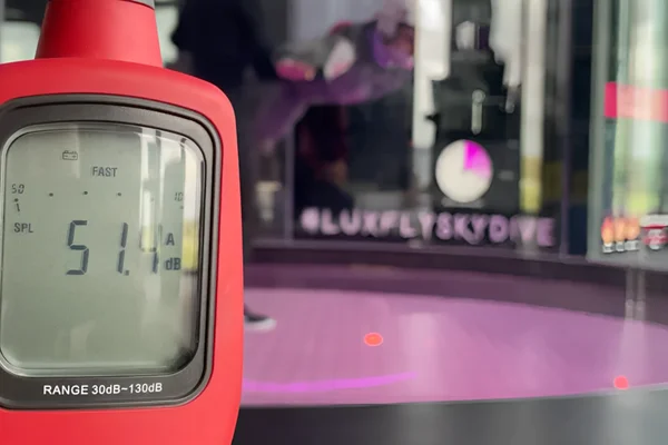
The pinnacle of German aerodynamic engineering. Featuring revolutionary passive ventilation technology, the TT45 delivers up to 60% energy savings and the world’s quietest operation at just 51 dBA.

Chamber Diameter
4.5 m (14'9")
Max Speed
320 km/h
Power
1,260 kW
Noise Level
51 dBA
TT45 PRO

Key Features

World's quietest at 51 dBA
Achieves up to 60% energy savings versus competitor systems
Revolutionary passive ventilation cooling
High-velocity airflow reaching 320 km/h for elite performance
16m maximum glass height
Industry-leading aerodynamic efficiency (0.183 drag coefficient)

Technical Specifications

General
Chamber Diameter4.5 m (14'9")
Glass Height (Default)8 m (26'2")
Glass Height (Maximum)16 m (52'5")
Chamber Area15.9 sq.m.
Diffusion Rate2.12

Ideal Applications

World Championships

Engineer FAI-compliant facilities capable of hosting professional indoor skydiving competitions and leagues.

Professional Training

Provide precision airflow and turbulence-free conditions for elite skydiver progression and technical coaching.

Military Training

Facilitate safe, cost-effective, and realistic freefall simulation for paratroopers and defense personnel.

Premium Entertainment

High-end entertainment destinations

Ready to Start Your Project?

Collaborate with our Stuttgart-based engineering team to configure the ideal high-performance wind tunnel solution for your specific goals.

Equipment assembly(25)
assembly and installation of wind tunnel equipment(54)
Facility construction(18)
Human flight(86)
Professional skydivers and BASE athletes(59)
The image shows the assembly process of the structural components for the Luxfly building, including the iconic pink load-bearing beams.The image shows the assembly process of the structural components for the Luxfly building, including the iconic pink load-bearing beams.

Assembly of Luxfly's iconic pink load-bearing beams.

The image shows the assembly process of the structural components for the Luxfly building, including the iconic pink load-bearing beams.

1 / 25

The image shows the assembly process of the structural components for the Luxfly building, including the iconic pink load-bearing beams.
The photo captures the installation of a main axial fan unit for the Luxfly wind tunnel in Luxembourg. The assembly features a large-diameter rotor with carbon-fiber blades mounted on a vertical axis. A crane positions the fan component within the ductwork, surrounded by the facility's red steel support structure. This component powers the airflow for a TunnelTech TT45 PRO system.
The photo shows the glass-plastic components of the TT45 Pro wind tunnel's airjet (confusor) under assembly at the Luxfly facility. These elements are part of the aerodynamic system designed for stable, low-turbulence airflow.
The image shows the final assembly of the turning vanes in the lower duct section of the Luxfly wind tunnel. Turning vanes are used to redirect airflow efficiently within the recirculation loop, minimizing turbulence and pressure losses.
Installation and assembly of the confuser in the flight chamber of the TT45 Pro wind tunnel. The Confuzor is a critical aerodynamic component that ensures smooth airflow transition into the flight chamber.
A technician positions a curved FRP air duct section containing turning vanes during the assembly of the Luxfly wind tunnel. This component forms a corner of the TT45 PRO recirculating loop, designed to redirect airflow within the concrete structure. The installation process involves precise alignment of the composite ductwork using rigging chains to fit the building envelope.
Two installation technicians equipped with safety harnesses and rigging gear stand on the structural steel framework during the construction of the Luxfly indoor skydiving facility in Luxembourg. The personnel perform rigging operations at height to align the TunnelTech TT45 PRO wind tunnel components with the building's distinct pink bearing structure. To the right, the exterior surface of the vertical wind tunnel assembly is visible adjacent to the steel beams.
Large blue fan housing units containing stator vanes await installation at the Luxfly wind tunnel site in Luxembourg. A mobile crane operates adjacent to the facility's distinctive pink steel bearing structure. These heavy mechanical components form the static section of the axial fan assembly for the TT45 PRO system. The construction team stages the equipment on the ground before lifting it into the facility's return duct loop.
The photo shows a drone view of the assembly of a metal construction building for the LuxFly facility, part of the TT45 Pro wind tunnel installation.
The photo shows the assembly process of the Luxfly building, including the installation of nearby glass-plastic diffusers. These diffusers are part of the aerodynamic system, designed to optimize airflow and reduce turbulence within the wind tunnel structure.
The photo captures the assembly process of a TT45 Pro indoor skydiving wind tunnel at the Luxfly facility. Visible components include the flight chamber structure and sections of the FRP composite air ducts, designed for efficient airflow and noise reduction.
Unloading process of 12-ton axial fans at the WindAlps construction site in France. The image captures the heavy lifting operation required to position these massive airflow components for installation into the wind tunnel facility.
The photo shows a turning vane assembly being lifted by a crane from the building. In the background, a flight chamber diffuser with openings for lighting is visible. Turning vanes are used to redirect airflow within the recirculation loop, reducing turbulence and noise.
Assembly of the corner section of the air duct with turning vanes at the WindAlps construction site. Turning vanes are arranged to optimize airflow direction and reduce turbulence in the recirculation system.
This image displays assembled aluminum turning vanes positioned at the top of the flight chamber in a double-loop wind tunnel at the Windalps facility. These vanes form a triangular, house-like structure designed to split the vertical airflow into two separate paths, directing the air into the left and right return ducts. The facility is shown prior to the installation of the roof, allowing sunlight to illuminate the vane structure and internal coolant channels.
A vertical perspective looking down through the upper diffuser section of a TT45 PRO wind tunnel at the Wind Alps facility. The white paneled walls of the airflow circuit feature circular access ports and lead down to the flight chamber level. Below, rigging chains and blue construction machinery assist in the installation of the glass flight chamber components and steel connection flanges.
The upper steel framework of a TT45 PRO wind tunnel is shown during assembly at the WindAlps facility. Black hydraulic manifold pipes are installed on the duct corners, connecting to the active cooling system integrated within the turning vanes. These connections circulate water through the vanes to manage airflow temperature. The steel structure is mounted on a concrete foundation, illustrating the scale of the mechanical installation required for the 4.5-meter flight chamber system.
Assembly of the TT45 PRO flight chamber takes place at the Wind Alps facility. A spider crane positions the curved, multilayer glass panels onto the structural steel base to form the round, frameless flying area. Rigging cables suspend the upper metal ring while additional crates containing glass sections sit ready for installation in the background. This construction phase establishes the transparent flight zone characteristic of the TT45 PRO model.
A specialized spider crane equipped with a heavy-duty vacuum lifter positions a large curved glass panel for the TT45 PRO flight chamber. Industrial climbers suspended from the upper concrete ring guide the multilayer noise-absorbing glass into the steel framing, while technicians on scaffolding align the base. This assembly process at the Wind Alps facility in France constructs the transparent, cylindrical flying area of the recirculating wind tunnel.
Cooling water supply hoses connected to the turning vanes of the TT45 PRO wind tunnel at the WindAlps facility. The active cooling system utilizes these turning vanes as duct-integrated heat exchangers. Chilled water circulates through internal channels within the hollow aluminum vanes, absorbing heat generated by air friction and fan operation. This configuration enables thermal management directly within the duct corners without introducing additional aerodynamic drag or separate cooling coils into the airflow path.