Engineering Excellence
Explore the German engineering innovations that establish TunnelTech as the global benchmark for performance, energy efficiency, and operational reliability.
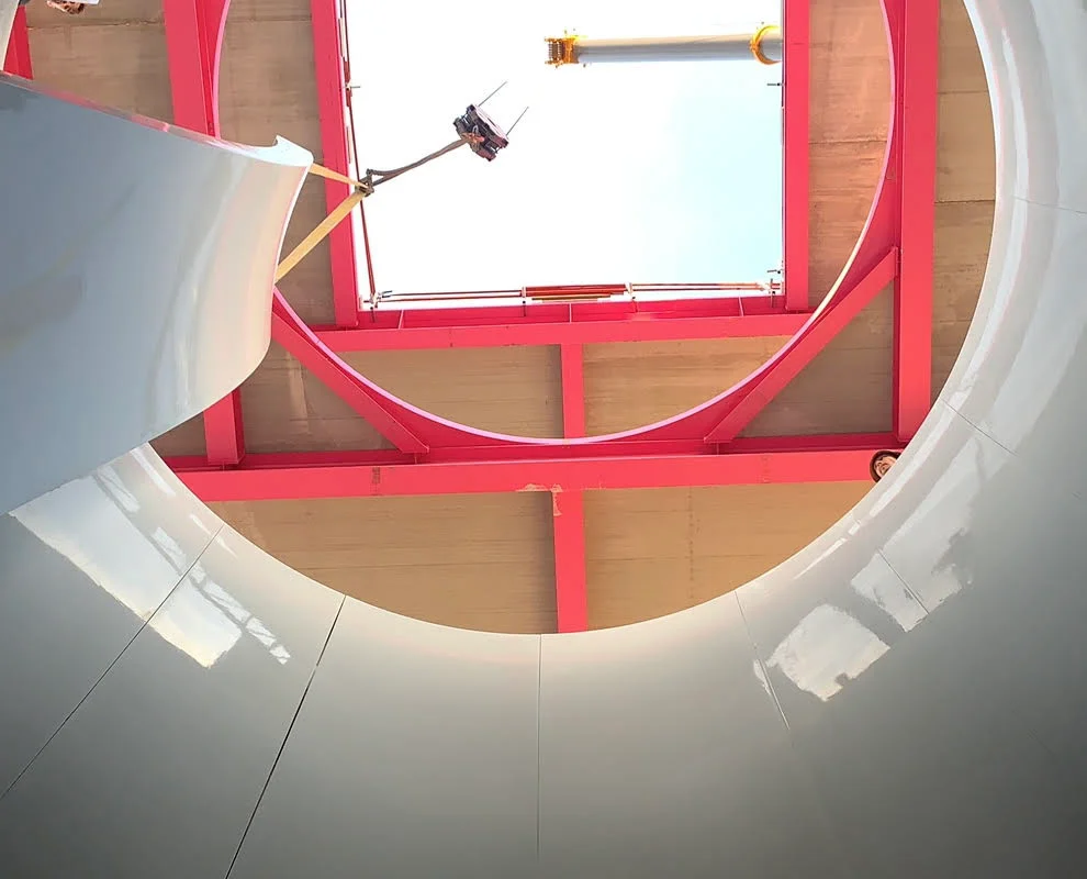
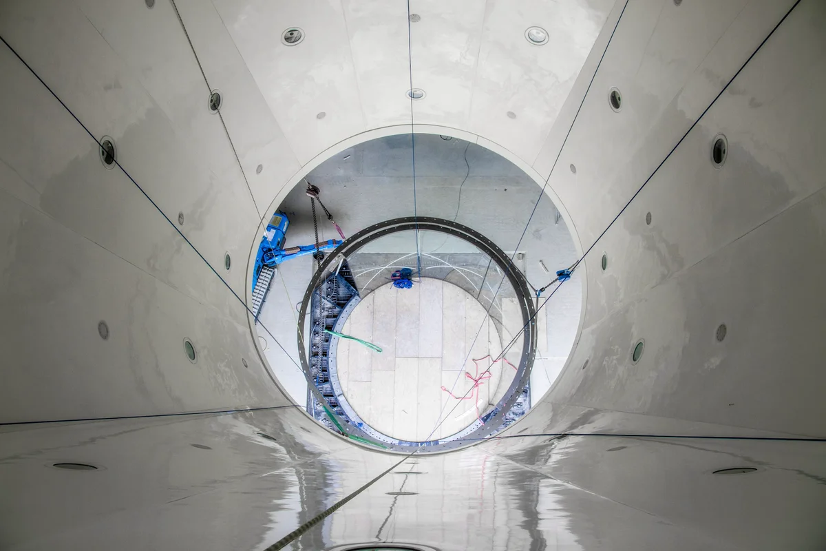
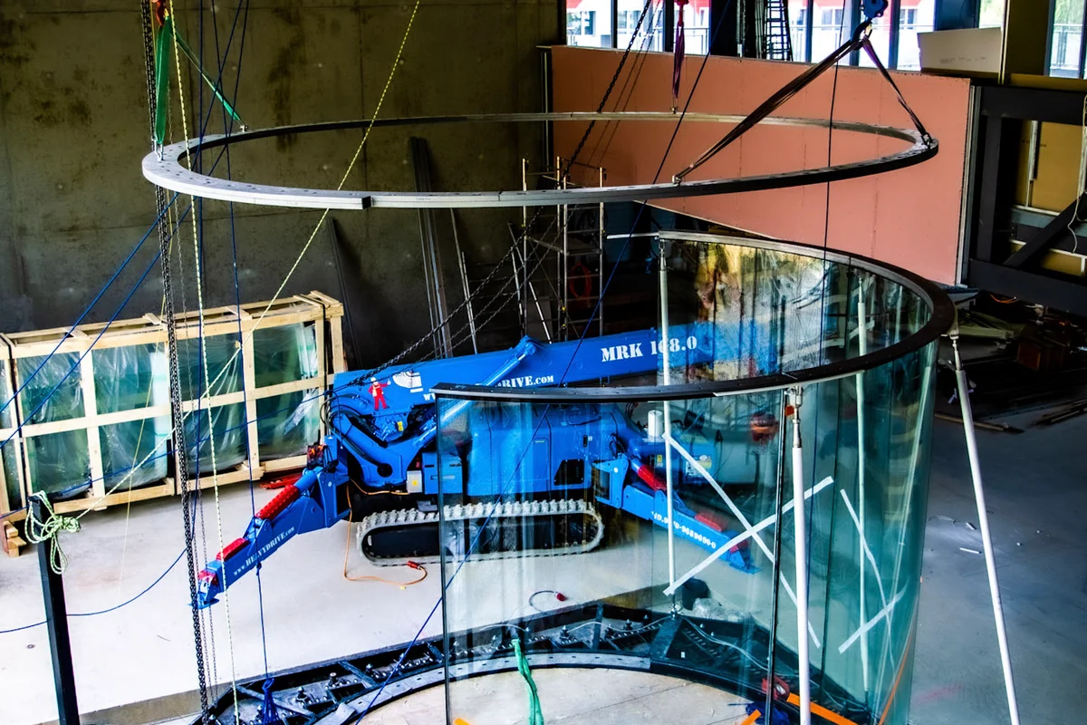
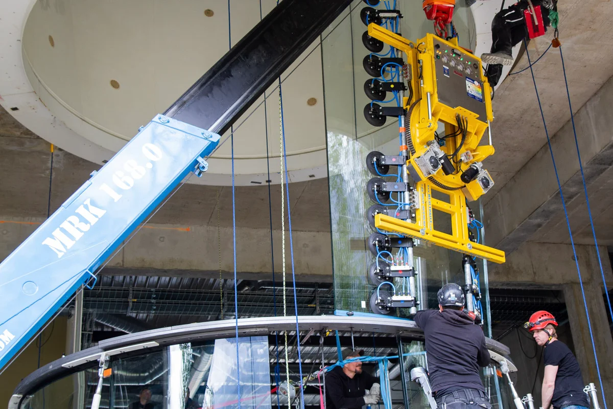
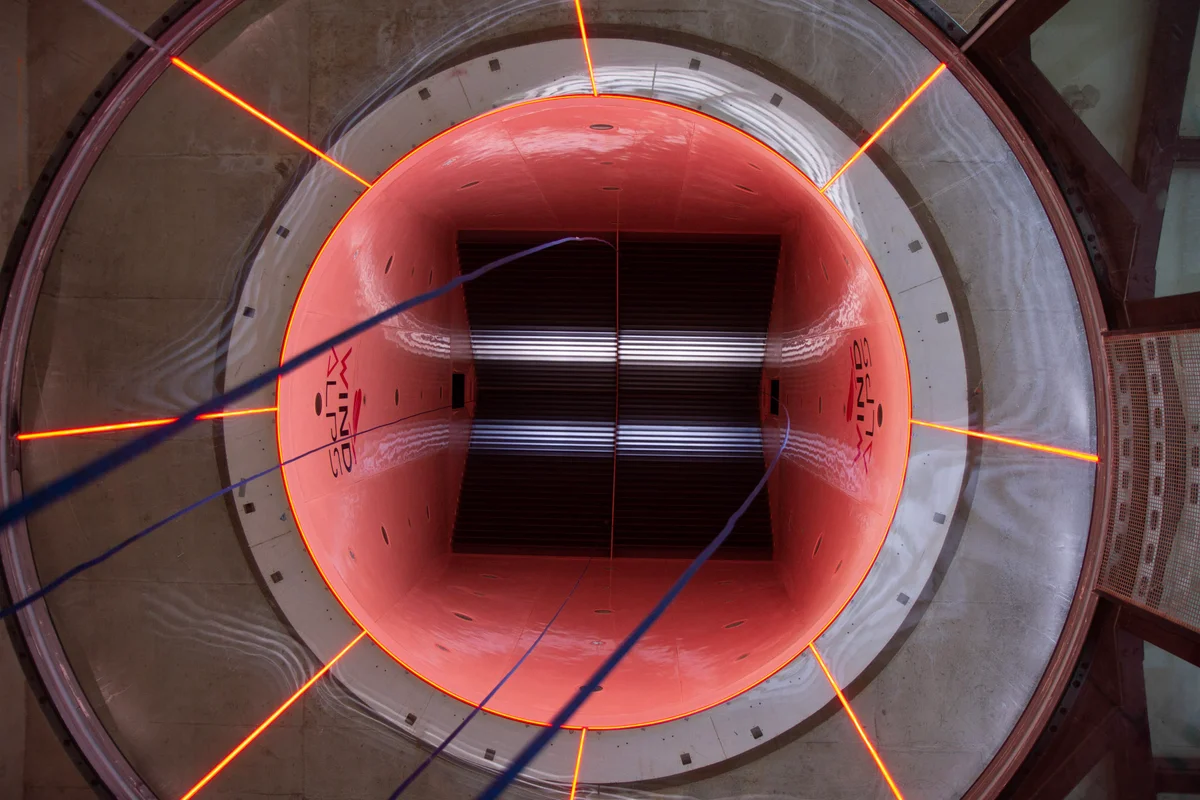
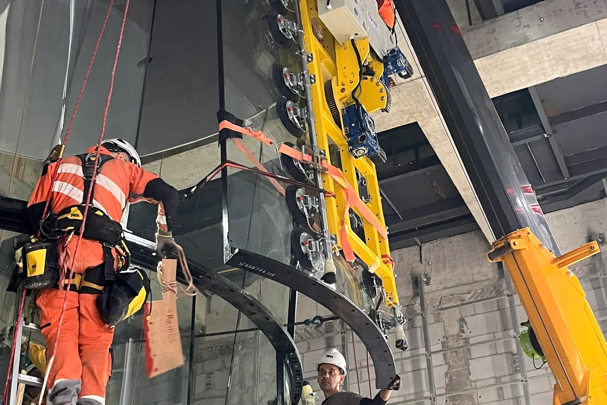
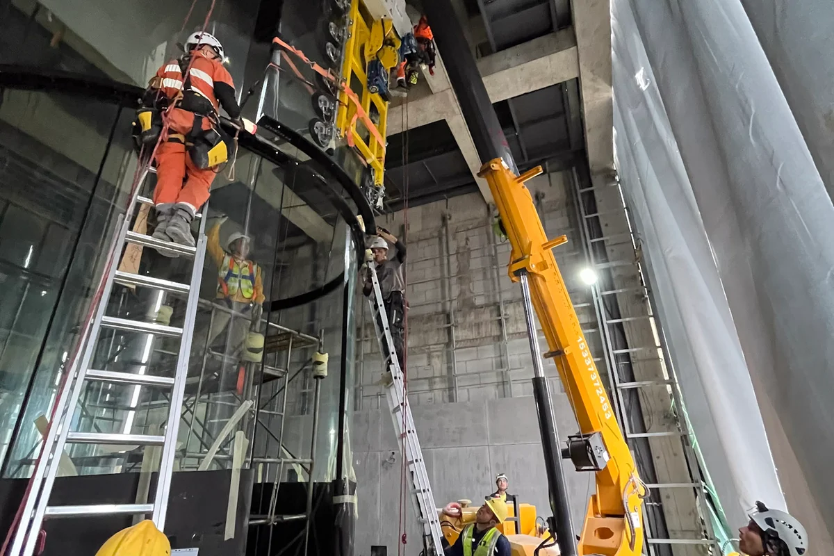
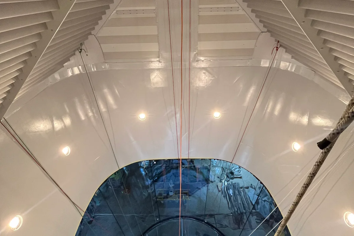
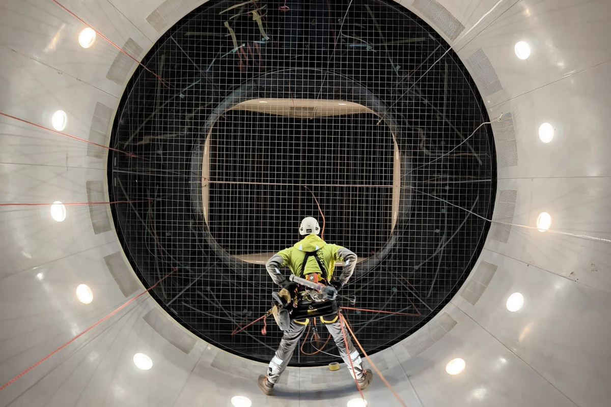
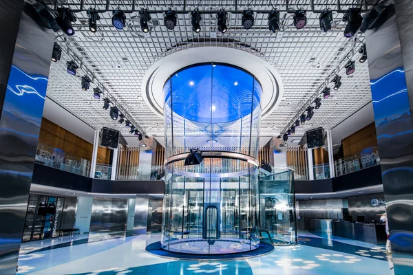
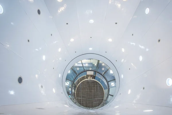
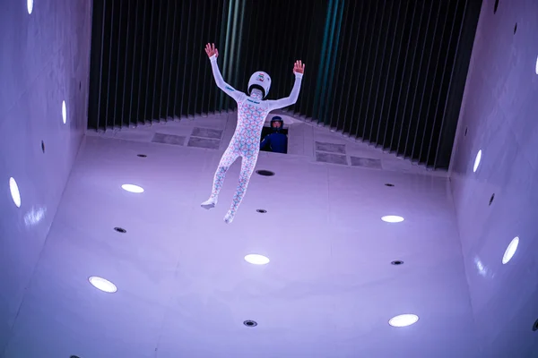
Flight Chamber
Where the magic happens - a revolutionary design for maximum safety and comfort.
- •Revolutionary safety net made of low-drag steel cables absorbs impact at the outer edge
- •Padded entrance prevents injuries and maintains even airflow
- •TT signature conical glass frameless section for 2x visible flying space
- •Perfectly round multilayer noise-absorbing glass for even airflow
- •Chamber height up to 24m with glass sections up to 8m
- •Airspeed reduction of 2.12x for critical safety
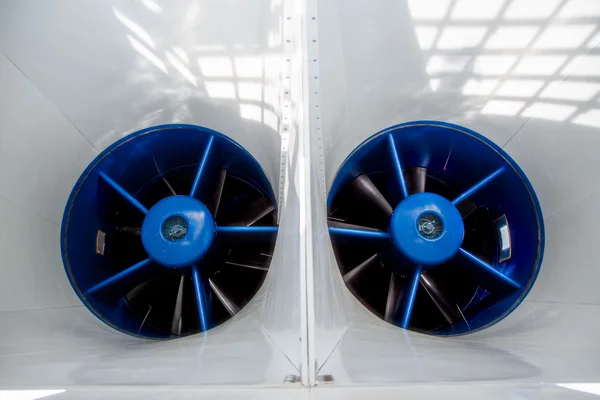
Axial Fans
The roaring heart of TunnelTech machines - meticulously calculated and manufactured with pinpoint accuracy. In 16 years and millions of operating hours they showcase a spotless track record with not one part or bearing ever replaced.
- •Strategic alliance with EVG Lufttechnik - 40+ years of aerodynamics expertise
- •Carbon fiber impellers redefine energy efficiency and vibration control
- •Large diameter and low RPM for minimal noise and vibration
- •ABB or Siemens electric motors for 30+ year expected lifespan
- •Complete diagnostic sensors for vibration, temperature, oil level
- •Automatic lubrication and individual frequency converters
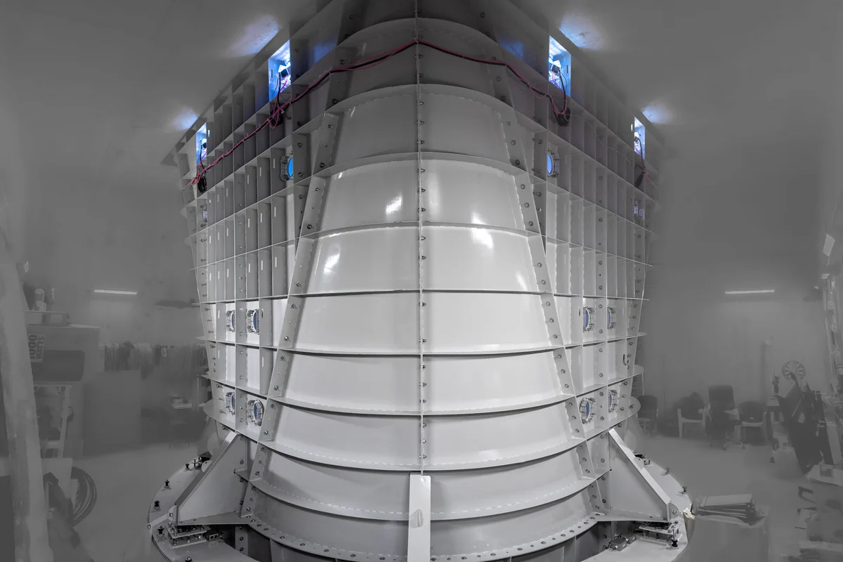
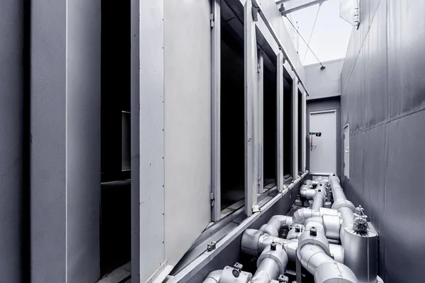
FRP Composite Airducts
Just like every exceptional sailboat is built around perfect streamlined shape, wind tunnel efficiency relies upon honed aerodynamic lines to guide unobstructed airflow from the motors to the flight chamber and back.
- •Highest degree precision for smooth transitions between tunnel sections
- •Eliminates near-wall turbulence - primary cause of noise and vibration
- •Sandwich structure absorbs sound waves vs. transmitting them
- •No uncontrolled resonance peaks common in conventional air ducts
- •Lowest Darcy-Weißbach Friction Factor (0.185) in the industry
- •Enables installation in demanding locations like shopping centers
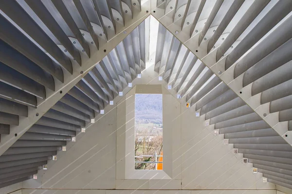
Turning Vanes
The cornerstone of wind tunnel efficiency. Classic NASA research shows that up to 30% of energy losses in a tunnel may appear due to poor turning vane design, insufficient frequency within vanes assembly and inappropriate mounting.
- •Meticulously calculated profile for optimal airflow guidance
- •Proper frequency within vanes assembly prevents turbulence
- •Appropriate mounting for maximum efficiency
- •Hollow design enables active cooling integration
- •Dramatically affects airflow quality - reducing or inducing turbulence
- •Up to 30% energy savings with proper design
Passive Cooling (Ventilation)
Otherwise known as 'ventilation', passive cooling reduces energy expenses by as much as 30-35%. By exchanging air with atmosphere this approach completely eliminates the need for costly chiller use, their maintenance and associated capital expenses.
- •Replaces up to 20% of circulating airflow with fresh air
- •Effectively cools system in temperatures below 30°C
- •Reduces total energy consumption by up to 30-35%
- •Eliminates need for expensive chiller equipment
- •No chiller maintenance costs
- •Up to 60% less power consumption due to outright ventilation
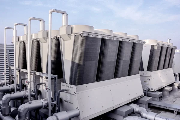
Active Cooling System
For hot climates and ultra-quiet operation near residential areas - cooling fluid is supplied through hollow turning vanes that act as heat exchangers.
- •Cooling fluid supplied through hollow turning vanes
- •Vanes act as heat exchangers for uniform airflow cooling
- •Eliminates turbulence from traditional cooling methods
- •Enables operation in any extreme climate
- •Noise emissions as low as 51 dBA
- •Allows installation in close proximity to residential areas (30m)
BASE Jumping Chamber
Located at the top of the wind tunnel, the BASE chamber is an indispensable tool for professional parachute training. It provides a secondary entrance to the flight chamber, allowing practice of controlled exits from aircraft in a safe environment.
- •Secondary entrance at the top of the flight chamber for realistic exit training
- •2x wind speed reduction at the door for safer training conditions
- •Only chamber suitable for training with a stabilizing parachute
- •Significantly increases safety during training sessions
- •Can be designed to resemble an aircraft cabin upon request
- •Full automation and safety systems available
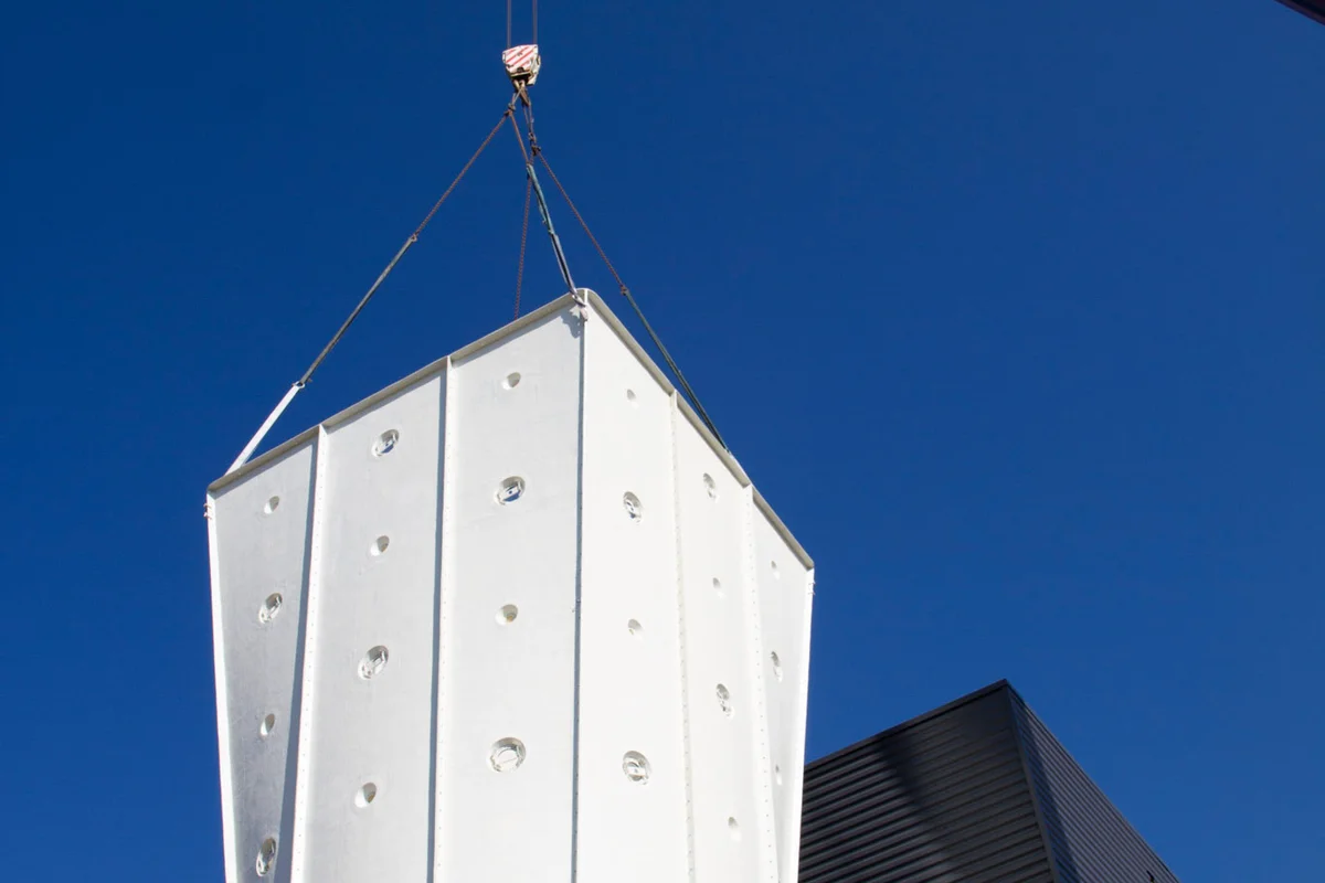
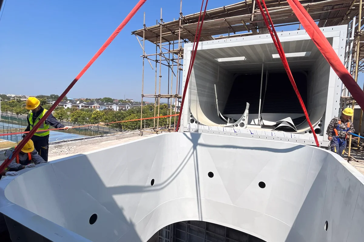
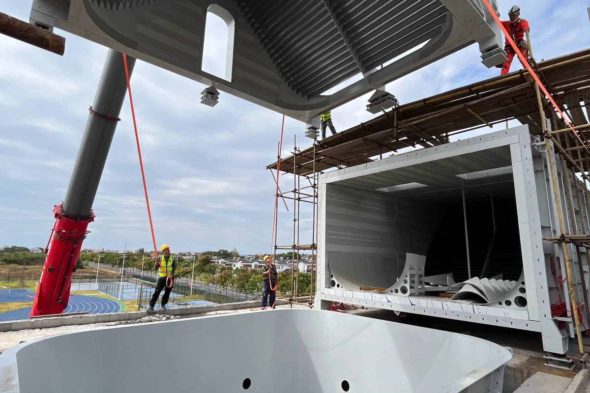
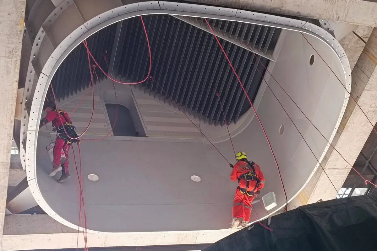
Crane lifting FRP flight chamber diffuser section with lighting ports at Windalps.
A mobile crane lifts a white, faceted FRP (fiberglass) diffuser segment into position at the Windalps facility in France. This component constitutes the upper section of the flight chamber, situated directly above the glass flying zone. The structure includes distinct circular ports designed for the installation of lighting elements. As part of the recirculating loop, this diffuser expands the airflow cross-section to reduce air velocity as it exits the flight chamber.
2 / 15