Overview
Introduction to Turning Vanes
In the realm of airflow management, the design of duct corners plays a key role in the efficiency and functionality of ventilation, HVAC systems, and wind tunnels. When air is forced to make a sharp turn, as is often required in ductwork, it encounters increased hydraulic resistance, leading to higher pressure losses and turbulence. This not only compromises the system’s efficiency by demanding more energy to maintain airflow but also impacts the structural integrity of the ductwork due to the uneven pressures exerted by turbulent flows.
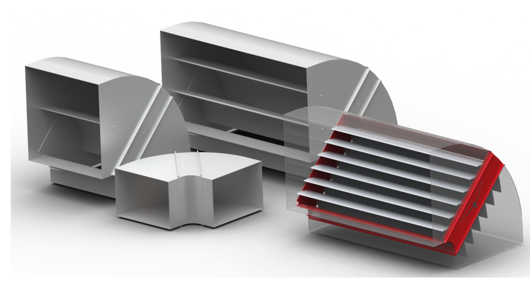
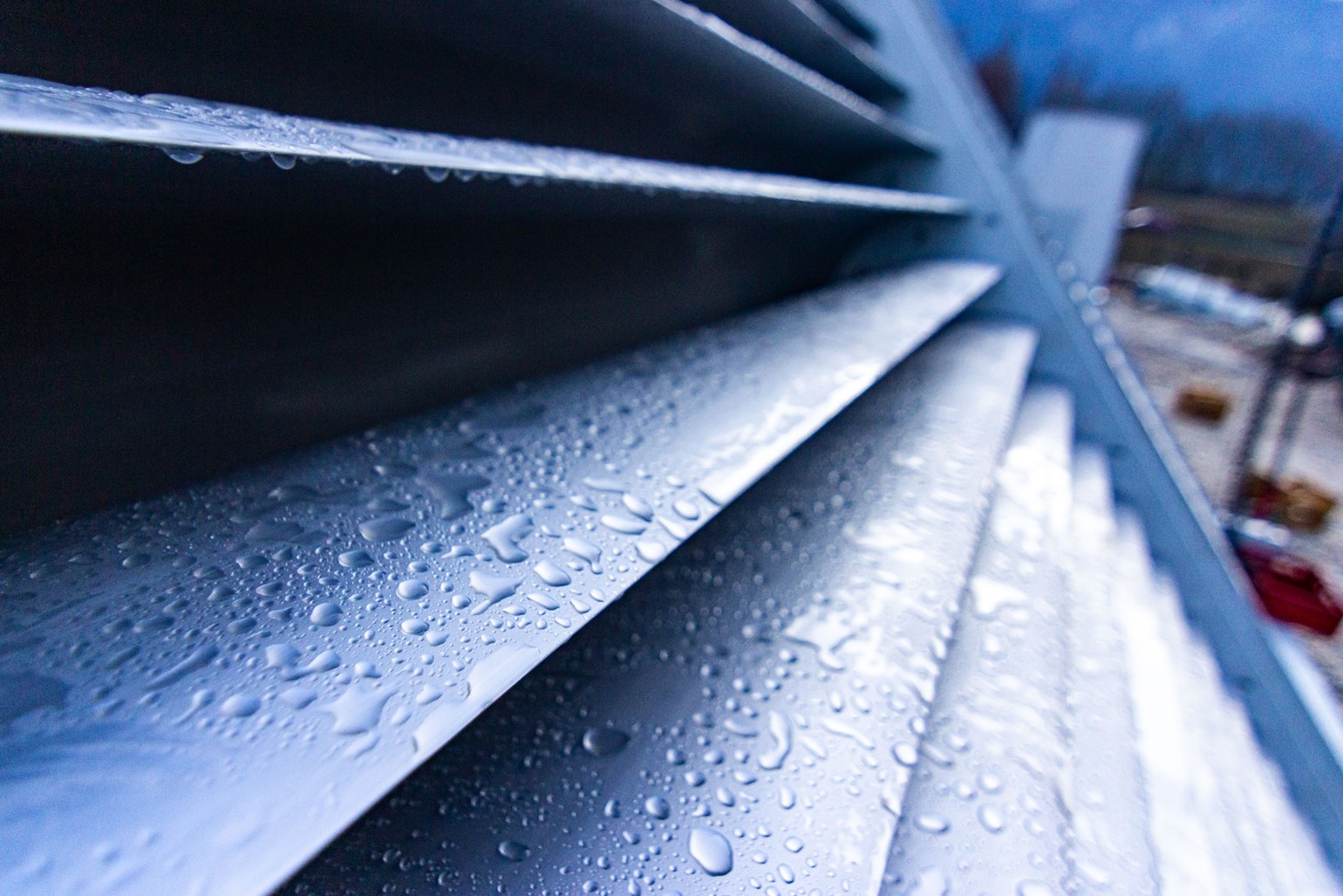
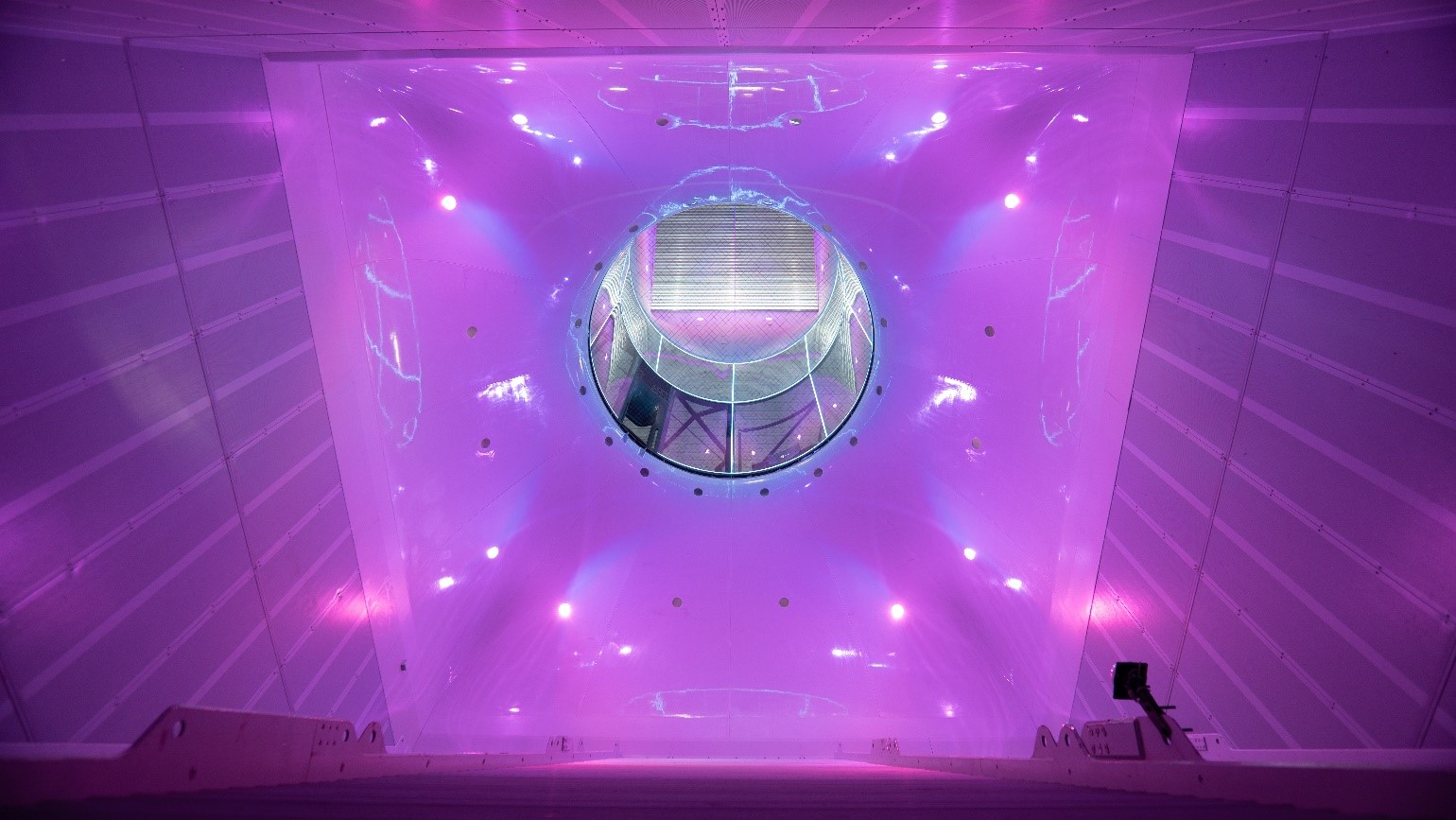
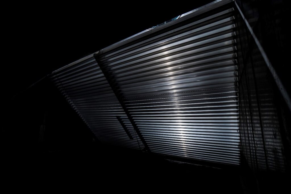
This is where turning vanes, also known as corner vanes or guiding vanes, come into play (Fig.1). Designed to be installed within the corners, duct corner vanes allow the air to navigate the turn with minimal resistance, effectively reducing pressure losses and mitigating turbulence without the need for the additional space that smooth radius-bends demand. This makes turning vanes an ideal solution for managing airflow efficiently in a compact space.

High-performance guidevane sections competing generic HVAC solutions.
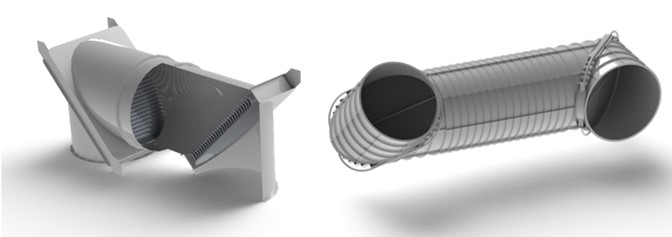
The traditional solution to overcome the mentioned harmful phenomena of increased turbulence, pressure loss and noise in a steeply curved duct is to design radial duct elbows (Fig.2 and Fig.4, case 2). These elbows, while effective in some mitigation of turbulence, noise, and pressure losses (which are common in a sharp bend as seen in Fig.4, case 1), have their own set of problems.
Several traditional ventilation ductworks with a turn made of smoothly curved sheet metal with bent flow directors is presented in Fig.2 on the left. The picture represents few examples of standard variants commonly used in HVAC ducts, e.g. compliant with DW144 ductwork standards.
Such duct solutions are common and cost-effective for small applications in civil engineering, small business and low-power HVAC systems where energy cost is not a significant factor. However, this design is not a good solution for ventilation and cooling systems in medium and large scale and high-capacity power generation, metallurgy, turbomachinery, heat exchangers, waste heat recovery and modern green and renewable energy applications where hydraulic efficiency and energy savings are a must.
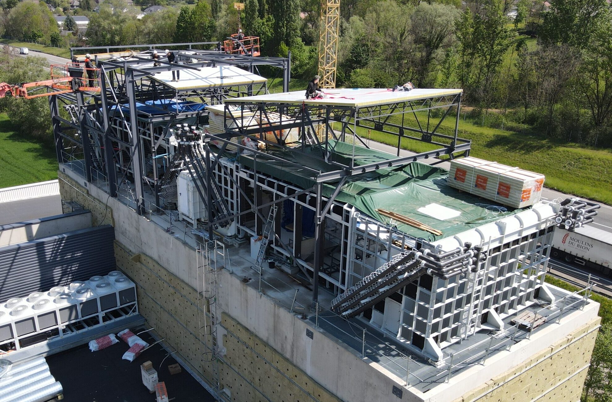
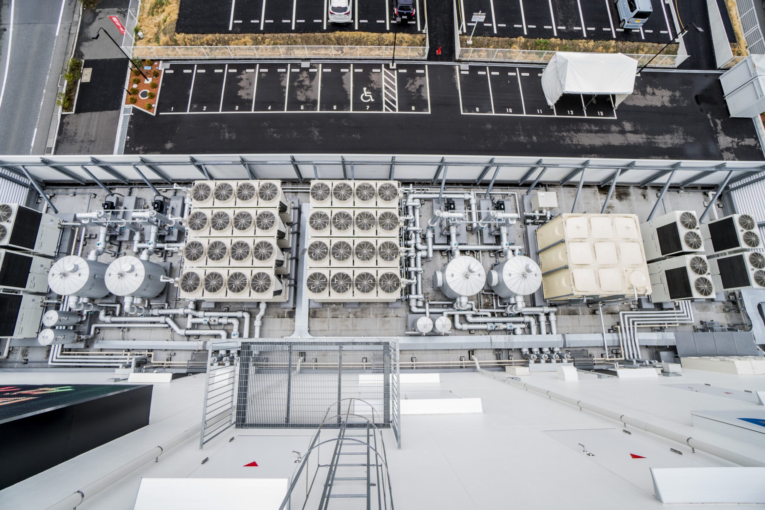
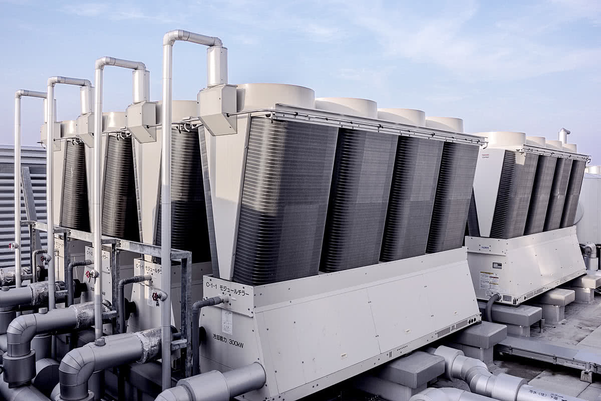
However, there is no need to build a custom non-standard duct every time the energy consumption of a hydraulic network needs to be optimized to perfection. The same Figure 2 on the right shows a variant of Tunnel Tech’s diagonal guiding vane section, which is energy efficient, low noise and low turbulence, while meeting industry standards for HVAC systems, but also can be used in large-scale and high-power industrial use cases. An example of a large-scale facility where the diagonal turning vane section can be easily integrated is shown in Fig.3.
Core Principles & Efficiency
Turning Vane design for pressure drop turbulence and noise reduction
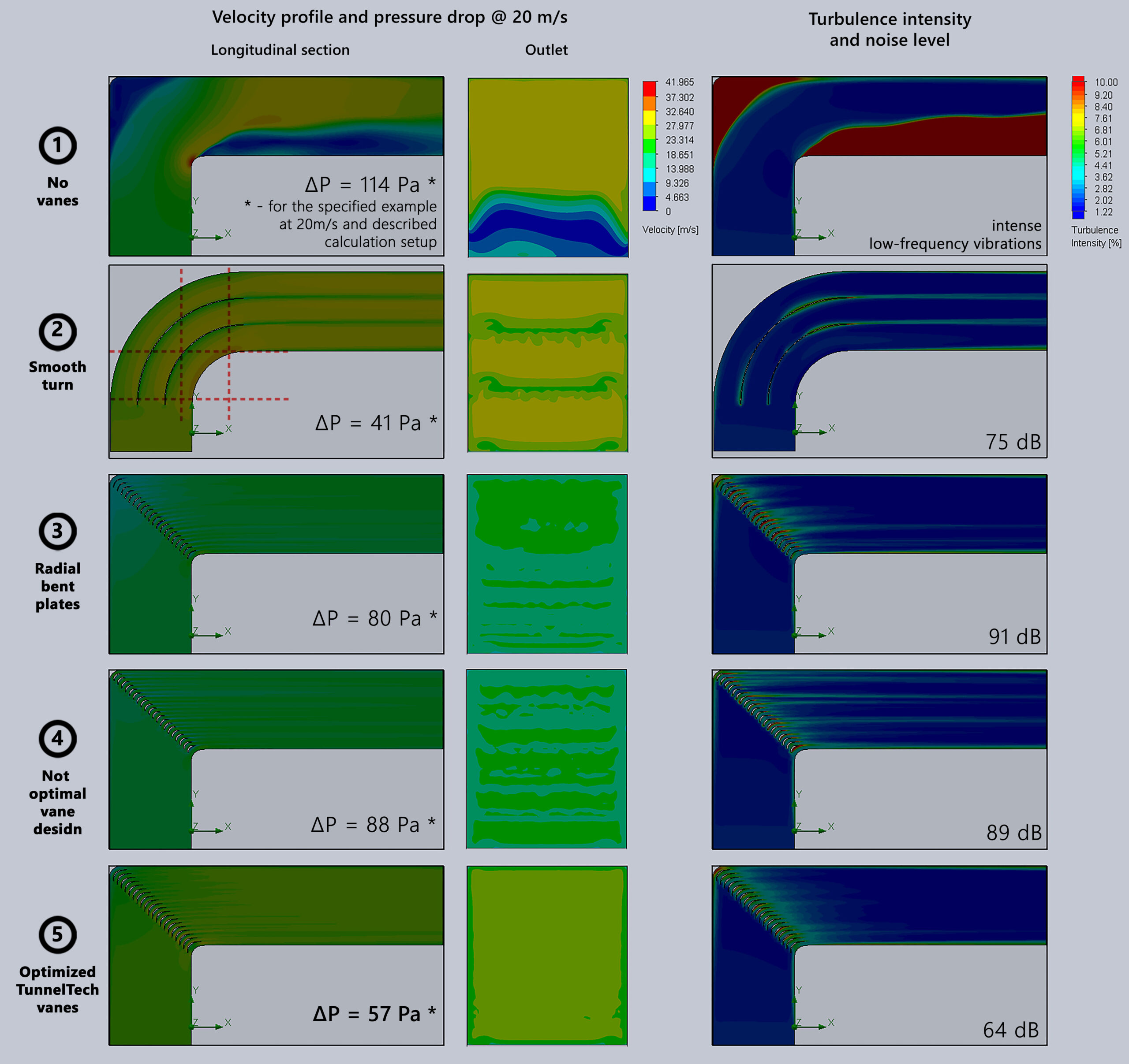
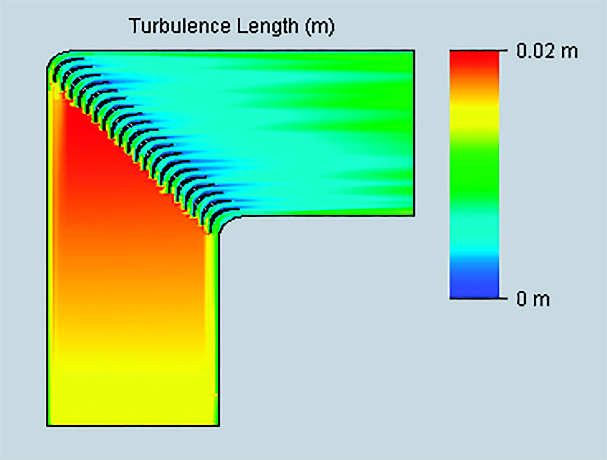
For comparison of different turning corner designs, the pressure drops (ΔP) and CFD-simulated flow patterns are given in the Fig.4 below. The inlet airflow velocity of 20 m/s and 2×2 m square duct were chosen as a demonstrational example. The speed range of 20 m/s was chosen for demonstration purposes, since normally professional-grade vertical wind tunnels for indoor skydiving operate most of the time in modes, whereby the flow velocity in the rotating section varies in between 10 and 30 m/s. CFD-calculations were performed for 1 standard atmosphere at 20 C and zero air humidity with a compressible gas and an adiabatic wall with a roughness of 250 µm. The mesh of 6 to 10 mln. cells per domain was used. Flat Inlet profile and 2% turbulence were applied at the inlet boundary. Turbulence was treated using k-ε model.
NB! Please note that the illustrations shown in Fig.4 are particular examples, presented solely for the purpose of illustrating the operating principles and comparing few types of rotary corner sections. These cases cannot be construed as general for absolutely every use case. For every real ventilation system or other hydraulic network, specific hydraulic parameters, duct size and shape, roughness and structural irregularities, flow inhomogeneities and exact physical gas parameters must be taken into account for every computational point. You can order such a calculation for a specific system by contacting us.
The following design cases are described:
- Corner section without guiding vanes.
- Smoothly curved corner section (r = ½ of the duct height) with radial-bent flow directors. Pressure drop depends also on the number and on the geometry of the duct spacers. The example with minimized number of optimally shaped airflow splitter plates is shown.
- Simple radially curved thin plates (10-20mm thick).
- Typical not-optimized turning vanes of closest competitors.
- Tunnel Tech’s turning vanes (TTE-TV) with an optimized profile.
The most significant problem of the round-curved ducts with small number of simple bent plate separators (or without guiding vanes at all) is the pressure and velocity distribution pattern at the turning section exit (Fig.4, case 2, see the outlet cross-section). This pattern shows that the velocity will increase from the outer wall to inner wall of each flow subdomain, leading to nonuniform flow, big turbulence and noise. The smaller the turn radius, the greater is the possibility of flow separation, pressure and velocity field distortion, noise level and pressure drop value.
The only way to overcome these issues is a big curvature radius of such a corner section and increase in the number of air flow guiding vanes. Here comes the second problem – the increased space required to accommodate such bends and the material cost of several radial airduct spacers, sized to the duct cross-section. In large duct systems, implementing smooth radius-bends can lead to unreasonably large structures, making this approach impractical in many scenarios, especially where space is at a premium. The additional space needed is shown by the dashed lines in Fig.4, case 2 below. One must increase the height and width of each turn by minimum of ½ of the duct size. For recirculating wind tunnels it means the increase of building dimensions by several meters in each direction, what leads to higher ductwork costs and higher capital investments. In addition, each flow divider will cost the same as the duct wall.
The optimal solution for wind tunnels and industrial ventilation are turning section rotary vanes with a wing profile arranged along the diagonal as depicted in Figure 4, cases 3-5.
All CFD-pictures above correspond to the airduct corner section with 2x2m inlet at 20 m/s air flow velocity, as an example, most relevant to the indoor skydiving and low-speed subsonic wind tunnel’s use cases.
Figure 4 case 3 shows a corner section with simple guiding vanes made of thin bent metal sheets. Fig.4 case 4 is the best example of rotary vanes available from TunnelTech’s closest competitors. Both have a smaller chord length and an unoptimized airfoil shape, resulting in what appears to be residual flow non-uniformity at the section exit, greater aerodynamic resistance and air duct noise. Thin vanes made of simple bent metal sheets usually exceed the permissible noise levels even at low air speed, and an option with a thick and short profile with low chord-to-thickness ration will also have a smaller surface area, which is undesirable in applications where cooled turning vanes are used for heat transfer.
In the lower part of Figure 4 case 5, the airduct corner equipped with high-performance Tunnel Tech turning vanes (for ordering refer to the following p/n: TTE-TV-90) are shown. As can be seen from the cross-sections, the flow is more uniform in the case of properly profiled guide vanes, which leads to less pressure drop and low turbulence.
The outlet air pressure/velocity profile is also much better for Tunnel Tech’s corner sections equipped with long-chord vanes than in other cases. This results in unrivaled Tunnel Tech aerodynamic quality, as reflected in numerous reviews by professional skydivers and other customers.
All discussed above data, including the chord length and cooling options is available in Table 1 also.
| Table 1. Comparative parameters for cases 1-5 of Figure 4. | ||||||||||||||||||
|---|---|---|---|---|---|---|---|---|---|---|---|---|---|---|---|---|---|---|
|
Case / Vane type |
ΔP (Pa) (*) |
ξ (*) |
Chord
length (mm) |
Cooling |
||||||||||||||
|
1. No vanes, sharp turn |
ΔP = 114 |
ξ = 0.47 |
– |
No cooling |
||||||||||||||
|
2. Smoothly curved corner section |
ΔP = 41 |
ξ = 0.17 |
> 2000 |
No cooling |
||||||||||||||
|
3. Simple radially-curved thin plates |
ΔP = 80 |
ξ = 0.33 |
250 – 500 |
No cooling |
||||||||||||||
|
4. Closest competitors’ turning vanes, small chord |
ΔP = 88 |
ξ = 0.37 |
280 |
YES |
||||||||||||||
|
5. Tunnel Tech optimized turning vanes, large chord |
ΔP = 57 |
ξ = 0.24 |
500 |
YES |
||||||||||||||
|
|
|
|
|
|
|
|
|
|
|
|
|
|
|
|
|
|
|
|
(*) The values are valid only for the example shown @ 20 m/s, including 18m duct. For demonstration purposes.
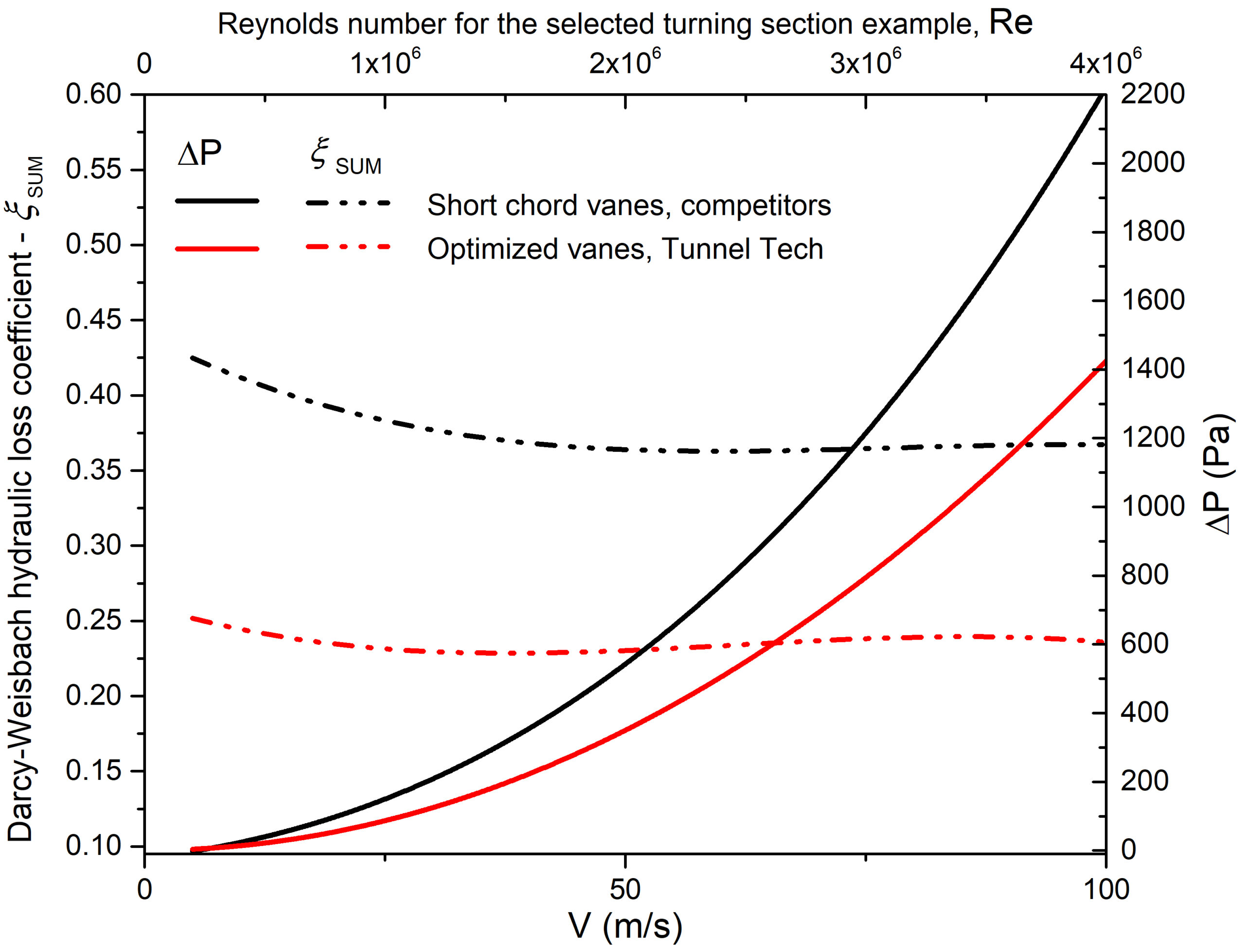
The values of the hydraulic loss coefficient for the speed range up to 100m/s for the duct turn section with TunnelTech and competitors’ vanes, with no variation due to the choice of initial data, are given in Fig.5.
More details on hydraulic losses along the duct length, local resistance and total hydraulic loss coefficient are given hereunder.
Mitigating Turbulence for Reliable Hydraulic and Structural Safety Calculations
Smooth and predictable pressure/velocity profile is especially important for applications where high turbulence or flow separation are not acceptable, such as experimental wind tunnels, indoor skydiving facilities, and high-power applications. These parasitic phenomena, as well as pressure pulsations caused by flow separation and large-scale turbulence, are also unacceptable in installations that require the absence of acoustically induced vibrations and where any static pressure deviations are not allowed due to air -duct structural stability requirements. Additionally, these turbulent flows are a common source of noise, further detracting from the system’s overall performance and comfort provided to the end-users.
It should also be considered that flow irregularities tend to further develop and intensify, if special straighteners, honeycombs, deturbulization nets or other airflow management devices are not used [1-3]. Precise gas dynamic analysis requires to calculate the resistance of each next airduct element taking into account the real inlet pressure/velocity profile, which is generated in the previous element of the hydraulic network. For long hydraulic networks it is often impossible to perform a CFD simulation of the entire system due to the huge dimensions. For such a situation, approximate semi-empirical calculations involving fluid dimensionless numbers and geometry criteria [4] or software based on such methods are used. Also, FEA modeling to determine duct structural stability is typically performed with a stable static pressure field applied to the duct walls. Thus, severe flow irregularities developing downstream can also introduce error into safety-critical investigations of load-bearing structures.
Approximate methods usually do not deal with the distortion of the velocity profile at the inlet to the hydraulic network element, and at best take into account whether the profile is developed or uniform, as well as the boundary layer parameters. In wind tunnels and industrial ventilation systems, each flow turn can cause such non-uniformity, creating a strong flow swirl, leading to uncertainty in hydraulic resistance calculations in such long hydraulic networks. Therefore, it is certainly important that care should be taken to avoid the formation of large velocity profile irregularities wherever possible.
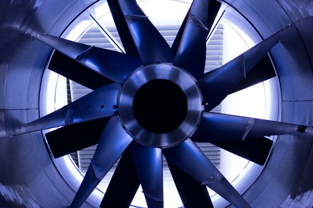
It can be seen in Fig.6 and from the above demonstrated that the parameters of turning sections with TunnelTech turning vanes are such that they do not create additional flow disturbances but can also be used to dampen swirls and non-uniformity downstream of the turning section. Thus, the rotary section with TunnelTech vanes can also act as an effective flow straightener, is installed after the axial fan, duct diffuser, heat exchanger, test section, branching or tapping into a duct, or any other turbulence generating object.
Local Resistance Coefficient
Turning corner’s local resistance characteristics can be calculated using the well-known Darcy-Weisbach equation:
Where:
ΔP – total pressure losses (pressure drop) in Pa;
ξ – local resistance (Darcy-Weissbach) coefficient;
ρ – fluid density (kg/m3);
V – fluid velocity at the inlet cross-section (m/s).
These parameters, which determine the energy efficiency of the air duct, are highly dependent on the turning vane design.
According to [4] the total resistance of a complex hydraulic element can be represented as a sum of the length friction resistance ξL and local resistance ξ0:
For a rectilinear air duct the length resistance is proportion to the length and inversely proportional to the hydraulic diameter, which is expressed by the formula:
[math] \xi_{L} = \frac{L}{D} \cdot f [/math]
where f is the Darcy friction factor.
In case of simple shaped pipes (i.e. circle, square, hexagonal), f can be expressed by a nonlinear dependence only on the Reynolds number – see Chapter 2 in [4] or https://en.wikipedia.org/wiki/Darcy–Weisbach_equation
The friction factor f for a simple round pipe (circle duct) with smooth walls, with a developed stabilized flow profile at the inlet and for turbulent regime (Reynolds numbers Re > 4*103) can be calculated by the formula:
[math] {\displaystyle f = {\textstyle \frac{1}{(1.81 \, \cdot \, lg( \textit{Re} ) – 1.64)^2 } } }[/math]
For real ducts, roughness must also be taken into account.
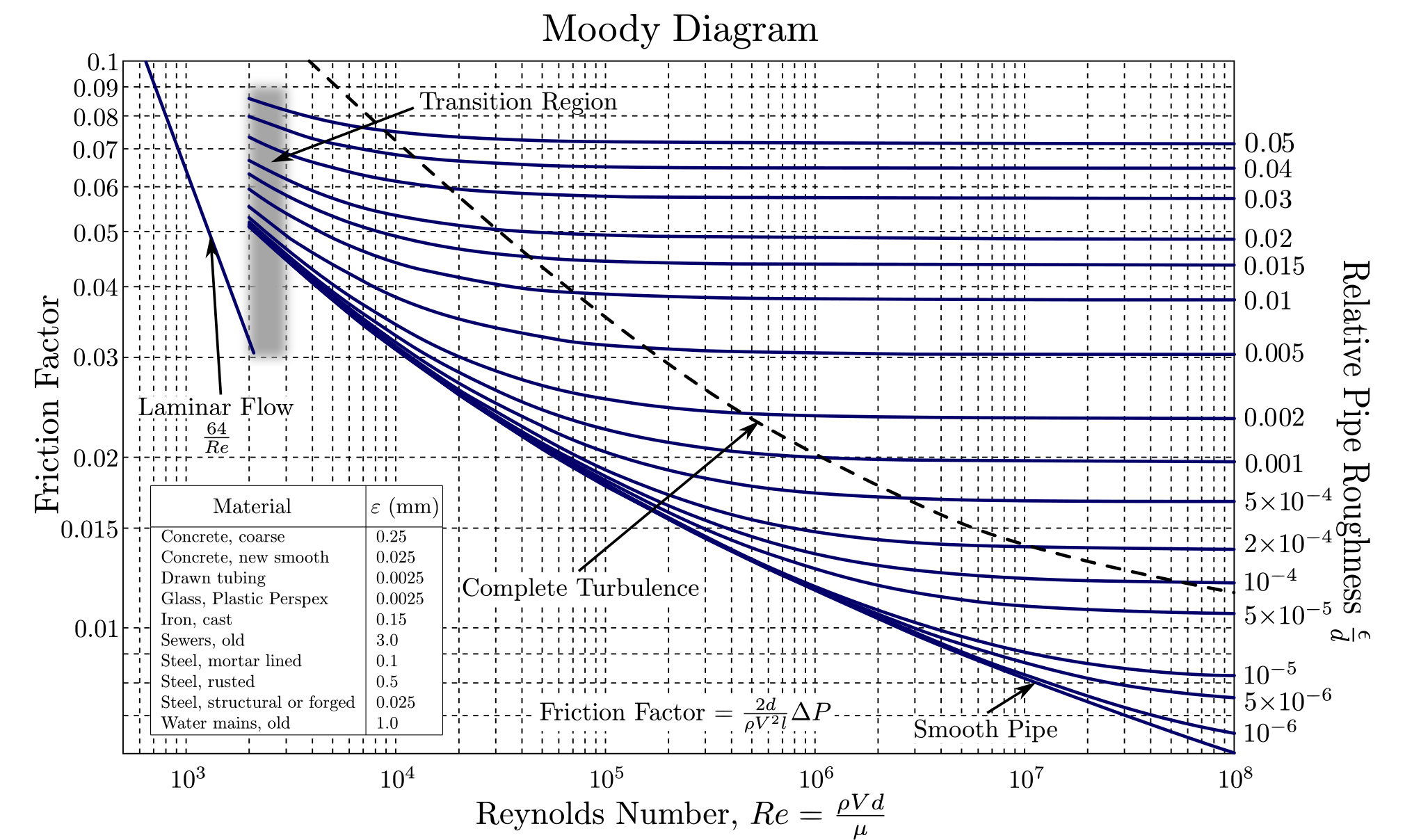
Fig.7 below shows a plot of Darcy friction factor versus Reynolds number Re for various relative wall roughness, first published by Ninkuradze in [5-8]. This graph is also known as Moody’s diagram [9] or Colebrook-White correlation [10-11]. Modern study for smooth pipes can be found in [12].
This diagram shows the complex dependence of f(Re) for a round pipe having different roughness. For square and other non-circular pipes, the diagram will be more complicate. Thus, flow regimes (Reynolds number) the duct shape and relative wall roughness must be taken into account.
In the case of real rough ducts, it is still possible to represent the total resistance the as a sum ξSUM = ξL + ξ0 of the length resistance and the local resistance.
This representation of the sum simplifies the study of duct parameters, since the local resistance ξ0 can be calculated for a simplified element geometry – for example, in a periodic formulation of the problem with a smaller calculation domain or in a 2D version of the problem. Note the huge size of the computational domain of the examples shown in Fig.4, where the section has a height of 3 and a length of 18 meters, and grid convergence begins to appear adequately at a size of more than 10 million mesh elements. A variant of the problem formulation with periodic or 2D conditions for these cases could have an order of magnitude smaller number of mesh elements, and the simplified calculation of each velocity point for the ΔP(v) graph would take only take a matter of minutes or even seconds rather than hours.
Thus, partitioning into the sum of two resistances can significantly simplify calculations – one can quickly determine the local resistance ξ0 mad then the length resistance ξL can be added. The latter can be quickly estimated from known tables or by approximate formulas using simplified equations based on dimensionless numbers and airduct geometry parameters. For hydraulic and duct network elements with abrupt changes in the flow direction, (angled elbows, smooth bends, bends at different angles with and without turning vanes), a similar approach and method is presented in Chapters 6-1 and 6-2 in the comprehensive Handbook of hydraulic resistence [4].
Product Highlights
Tunnel Tech’s air flow turning vanes (TTE-TV product) are at the forefront of this technology, offering unparalleled efficiency in airflow management. Our products are designed for a wide range of applications, from indoor skydiving facilities and wind tunnels to HVAC and ventilation systems, embodying the cutting-edge of aerodynamic design and energy efficiency.
Turning Vane Section Performance in Air Ducts
Tunnel Tech’s high-performance airflow guiding vanes set the industry standard for power and aerodynamic efficiency. Our energy-saving turning vanes are engineered to minimize aerodynamic friction, ensuring smooth airflow and reducing energy consumption.
TunnelTech’s turning vanes have excellent air duct local resistance characteristics. Resistance parameters, calculated using the Darcy-Weisbach equation, as described above, are presented in the following figures (see Fig.8 below) and in the Turning Vane Datasheet.
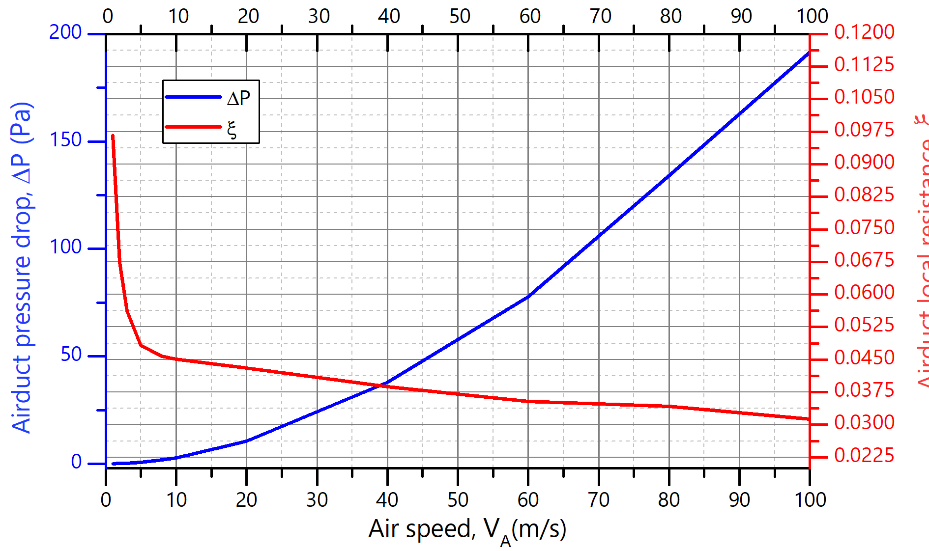
In general, for the case where the duct size is unknown, values are given for an idealized element featuring periodic lateral boundary conditions, without taking into account the contribution made by additional wall resistance along the length, roughness and the influence of other local parameters. In the Fig.8 the values for an idealized rotary corner element with Tunnel Tech vanes are given, which was calculated in the infinite periodic sequence approximation of 15 blade stack with periodic boundary conditions.
If the HVAC or other hydraulic system consists of ducts that do not generally change the cross-sectional shape of the flow area along the flow path, it is convenient to estimate the resistivity per unit length for approximate calculations (to be estimated, of course, for the entire velocity range):
[math] K_{L} = {\displaystyle \frac{\xi_L}{L} } = {\displaystyle \frac{ \textbf{ f } }{D_h} }[/math] ,
where Dh is a duct hydraulic diameter.
The value of KL is easy to determine from reference books, as discussed above. Thus, by multiplying this by the length, and adding local resistance values ξ0 obtained from datasheets or calculated independently, it is possible to quickly estimate the total pressure loss in the system.
[math] \xi_{SUM} = K_L \cdot L + \xi_0 [/math] ,
The above illustrative examples shown in Fig.4 of a 2×2 meter square duct with the gas parameters and roughness used in the calculation has a resistivity per unit length of the order of KL = ξL / L ~ 2.1 Pa. This value applies when evaluating a square duct without accounting for bends, vanes, or other internal equipment. For a full length of 21 meters that the air mass travels along the duct will give a pressure drop of ~44 Pascals. Adding to this the value shown in Fig.8 (11 Pa for a velocity of 20 m/s taken according to the Turning Vane Datasheet (Table A.2.1) gives a total resistance of 55 Pa for a real 2×2 square duct section with rotary vanes in it. This value is in good agreement with the value shown in Fig. 4, case 5.
More information on approximate ways to calculate duct resistances of any shape without using CFD methods can be easily found [4] or similar literature.
NB! Please note that the examples shown in Fig.4 are only a special case to demonstrate the operation of the rotary vanes and cannot be used to evaluate an arbitrary duct! Figure 8 is applicable in a broader context, however, the specific parameters of the client’s duct need to be considered. Each specific system needs a detailed analysis, which you can order from Tunnel Tech. For an accurate calculation of the duct hydraulic resistance and an expert assessment of the energy consumption of your ventilation or wind tunnel equipment, please contact us.
Additional information about services and RnD can also be found in the Services.
Turning Vane for industrial Cooling and Heating
Unique among guiding vanes for industrial air ducts, our products offer the capability to circulate coolant at a high flow rate, allowing for efficient cooling or heating of the air as it passes through the duct. This feature opens up new possibilities in thermal regulation for the use of indoor climate control vanes and low-resistance air-duct-integrated heat exchangers, providing our clients with versatile solutions for their airflow needs.
Evaluated using the HTCL (Heat Transfer Coefficient per Linear meter) calculation method, which quantifies the heat flux (in Watts) per meter of turning vane length for each Kelvin of logarithmic mean temperature difference (ΔTLMTD) between the external air and the corner vane coolant, our guiding vanes are engineered for effective heat dissipation across various airflow conditions, guaranteeing stable performance and temperature regulation.
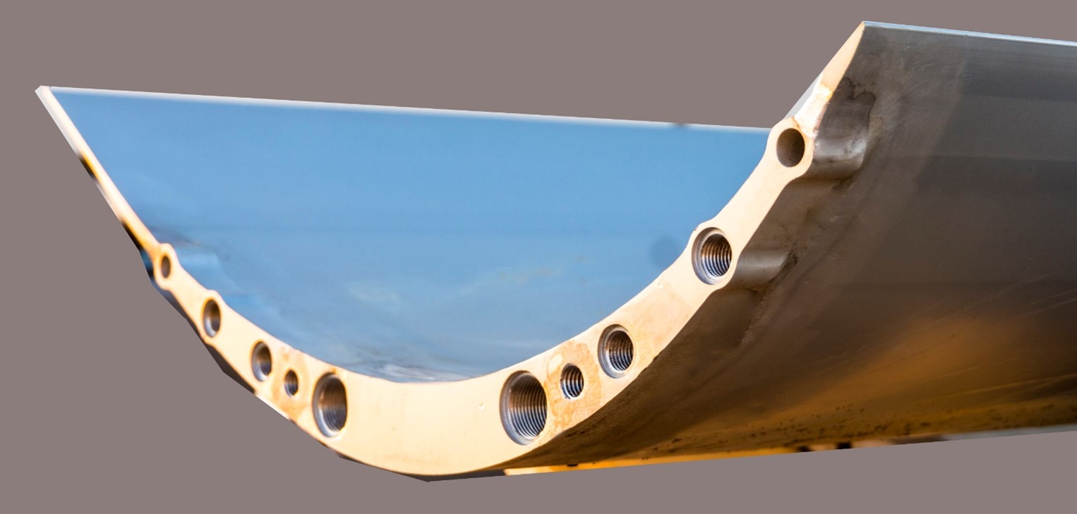
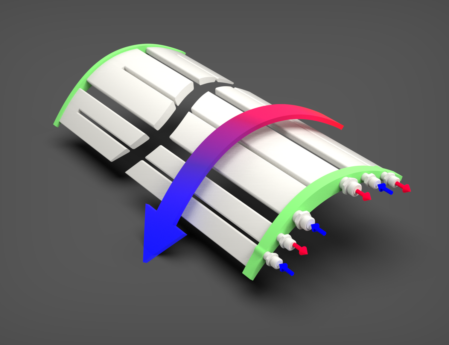
Heat Transfer Coefficient parameters for the water-cooled turning vanes are presented in the Fig.9, both for wet and for dry air, where ΔP [kPa] represents the water pressure difference between inlet and outlet vane ports (blue and red in Fig.10).
Turning vanes for Waste Heat recuperation
Cooled turning vanes with integrated heat exchange channels offer a versatile solution for waste heat recovery across a variety of applications. When integrated into heat exchange systems, these vanes can capture excess thermal energy that would otherwise be lost, transferring it to heat recuperation systems, thereby significantly enhancing overall system efficiency.
In practical applications, this technology can be utilized in multiple areas. For instance, in industrial processes, cooled turning vanes can recover waste heat from exhaust gases and redirect it to preheat incoming fluids or air, thereby reducing energy consumption. In HVAC systems, similar principles are employed through devices like heat recovery ventilators (HRVs) and energy recovery ventilators (ERVs), which transfer heat between exhaust and incoming air streams. This process minimizes the energy required to heat or cool incoming air, leading to substantial energy savings.
Additionally, cooled turning vanes can be integrated into systems used in power generation and renewable energy sectors. For example, in combined heat and power (CHP) systems, waste heat from electricity generation is recovered and used for heating purposes, improving the overall efficiency of the system. In geothermal energy systems, these vanes can help manage the thermal energy extracted from the earth, optimizing the heat transfer processes.
In green and renewable energy initiatives, waste heat recovery plays a critical role in reducing carbon footprints and enhancing the sustainability of energy systems. This approach aligns with lean manufacturing principles by improving resource efficiency and reducing operational costs through effective heat management. Furthermore, in ESG projects, incorporating such technologies demonstrates a commitment to minimizing environmental impact and optimizing resource use, aligning with broader sustainability goals.
Heat recuperation - Related projects
Tunnel Tech has extensive experience in implementing projects involving heat exchange and HVAC systems designed for waste heat recovery using cooled turning vanes. By integrating these vanes into heat exchange setups, engineered to capture and repurpose thermal energy that would otherwise be lost, Tunnel Tech enables more effective recovery of waste heat from various industrial and commercial processes. This approach not only improves energy efficiency but also supports sustainability goals by reducing energy consumption and operational costs.
References and related publications
Additional information on the design and optimization of rotary blades for wind tunnels, industrial ductworks, HVAC ducts and airflow management equipment, fan straighteners et.c. can be found at the links below:
- Baals, D.D., and W.R. Corliss. Wind Tunnels of NASA. NASA ; SP-440. Scientific and Technical Information Branch, National Aeronautics and Space Administration, 1981. https://books.google.rs/books?id=G0sCAAAAIAAJ.
- Barlow, J.B., W.H. Rae, and A. Pope. Low-Speed Wind Tunnel Testing. Wiley, 1999. https://books.google.rs/books?id=nUHWDwAAQBAJ.
- Pope, A., and K.L. Goin. High Speed Wind Tunnel Testing. Wiley, 1965. https://books.google.rs/books?id=yHFTAAAAMAAJ.
- Idelchik, I. E. “Handbook of Hydraulic Resistance, Revised and Augmented.” Begell House, 2008, https://www.begellhouse.com/ebook_platform/monograph/book/5877598576b05c67.html
- Nikuradse, J. 1933 Stromungsgesetz in rauhren rohren, vDI Forschungshefte 361. (English translation: Laws of flow in rough pipes). Technical report, NACA Technical Memorandum 1292. National Advisory Commission for Aeronautics (1950), Washington, DC. The data are available in https://ntrs.nasa.gov/citations/19930093938
- Nikuradse, J. (1931), Strömungswiderstand in rauhen Rohren. Z. angew. Math. Mech., 11: 409-411. https://doi.org/10.1002/zamm.19310110603
- Nikuradse, J. 1932 Laws of turbulent flow in smooth pipes (English translation). NASA TT F-10: 359 (1966).
- Nikuradse, J. 1930 Widerstandsgesetz und Geschwindigkeitsverteilung von turbulenten Wasserströmung in glatten und rauhen Rohren, Proc. 3rd Int. Cong. Appl. Mech., Stockholm, 239-248.
- Moody, L. F. 1944 Friction factors for pipe flow. Trans. ASME, 66, 671–684. https://doi.org/10.1115/1.4018140
- Colebrook, C. (1939) Turbulent Flow in Pipes, with Particular Reference to the Transition Region between the Smooth and Rough Pipe Laws. Journal of the Institution of Civil Engineers, Volume 11 Issue 4, FEBRUARY 1939, pp. 133-156 https://doi.org/10.1680/ijoti.1939.13150
- Colebrook, C. F. (February 1939). “Turbulent flow in pipes, with particular reference to the transition region between smooth and rough pipe laws”. Journal of the Institution of Civil Engineers. London. Volume 12 Issue 8, OCTOBER 1939, pp. 393-422 doi:1680/ijoti.1939.14509.
- McKeon, Beverley J., Chris J. Swanson, Mark V. Zagarola, Russell James Donnelly, and Alexander J. Smits. “Friction Factors for Smooth Pipe Flow.” Journal of Fluid Mechanics 511 (2004): 41–44. https://doi.org/10.1017/S0022112004009796.
- Mehta R.D., Bradshaw P. Design rules for small low speed wind tunnels. The Aeronautical Journal . 1979;83(827):443-453, https://doi.org/10.1017/S0001924000031985
- Cattafesta, Louis, Chris Bahr, and Jose Mathew. “Fundamentals of Wind-Tunnel Design.” In Encyclopedia of Aerospace Engineering. John Wiley & Sons, Ltd, 2010. https://doi.org/10.1002/9780470686652.eae532.
- Hurtado, J.P.; Villegas, B.; Pérez, S.; Acuña, E. Optimization Study of Guide Vanes for the Intake Fan-Duct Connection Using CFD. Processes 2021, 9, 1555. https://doi.org/10.3390/pr9091555 https://www.mdpi.com/2227-9717/9/9/1555
- Gelder, T.F., Moore, R.D., Sanz, J.M. and McFarland, E.R. Wind tunnel turning vanes of modern design. 24th Aerospace Science Meeting. NASA Technical Memorandum, AIAA Paper 86-0044. Reno, Nevada, January 1986. https://api.semanticscholar.org/CorpusID:108506839.
- Schirf, Collin. “Optimization of Expanding Turning Vanes by Bezier Curve Parameterization,”, Master Dissertation, University of Maryland, 2019. https://doi.org/10.13016/5x1x-gxhz
- Almeida, Odenir De, Frederico Carnevalli De Miranda, Olivio Ferreira Neto, and Fernanda Guimarães Saad. “Low Subsonic Wind Tunnel – Design and Construction.” Journal of Aerospace Technology and Management 10 (February 26, 2018). https://doi.org/10.5028/jatm.v10.716.
- Modi, P. P., and S. Jayanti. “Pressure Losses and Flow Maldistribution in Ducts with Sharp Bends.” Chemical Engineering Research and Design 82, no. 3 (2004): 321–31. https://doi.org/10.1205/026387604322870435.
- Kotb, N. A. E., M. R. Mokhtarzadeh‐Dehghan, and A. J. Ward‐Smith. “A Numerical Study of Laminar and Turbulent Flows in a Two‐dimensional Bend with or without a Guide Vane.” International Journal for Numerical Methods in Engineering 26, no. 1 (January 1988): 245–62. https://doi.org/10.1002/nme.1620260117.
- Sahlin, A.; Johansson, A.V. Design of guide vanes for minimizing the pressure loss in sharp bends. Fluids A Fluid Dyn. 1991, 3, 1934–1940.
- Crawford, N.M.; Cunningham, G.Y. Prediction of Pressure Drop for Turbulent Fluid Flow in 90° Bends; Sage: London, UK, 2003; pp. 153–155
- Kumar, S.; Nandi, N. Change in Flow Separation and Velocity Distribution Due to Effect of guide vane installed in a 90° pipe bend. Mech. Eng. 2017, 21, 353–361.
See also:
- Moody’s chart: https://en.wikipedia.org/wiki/Moody_chart
- Darcy-Weisbach: https://en.wikipedia.org/wiki/Darcy–Weisbach_equation
- Friction factor https://en.wikipedia.org/wiki/Fanning_friction_factor, https://en.wikipedia.org/wiki/Darcy_friction_factor_formulae
- Friction loss: https://en.wikipedia.org/wiki/Friction_loss
Applications
Tunnel Tech’s aerodynamically optimized turning vanes offer unparalleled versatility and efficiency, suitable for a wide array of applications where airflow management is crucial. Our customizable air guide vanes are designed to integrate seamlessly into various systems, reducing energy consumption, minimizing noise, and optimizing aerodynamic performance. Below, we explore the diverse applications of our turning vanes, highlighting their benefits across different industries and scenarios.
Wind Tunnels
| Indoor Skydiving Facilities | Enhance the flying experience with reduced turbulence and energy-efficient operation; |
| Aerospace Testing | Achieve precise airflow control for accurate aerodynamic testing; |
| Automotive | Aerodynamic Testing Optimize vehicle design with improved airflow management; |
HVAC Systems
| Commercial Buildings | Ductwork optimization; Energy efficiency; Reducing operational costs; Enhancing health and safety by efficiently managing air quality and temperature; |
| Residential Complexes | Ensure comfortable living environments with optimal air quality and flow; Enhancing health and safety; |
| Data Centers | Thermal management airflow vanes maintain critical temperature and humidity levels for server performance and longevity; |
Civil Engineering Ventilation Systems
| Hospitals and Healthcare Facilities | Quiet operation turning vanes provide vital air quality control to protect patients and staff; Enhancing health and safety by efficiently managing air quality and temperature |
| Educational Institutions | Create conducive learning environments through improved air circulation |
Environmental Control
| Electronics Bio-tech Food-tech and other Hi-tech Facilities / Clean Rooms | Regulate temperature and humidity for high-tech and demanding production; Air conditioning guiding vanes maintain stringent airflow standards for manufacturing and research |
| Sporting Arenas | Ensure comfort and safety for athletes and spectators alike |
Industrial and Specialized Applications
| Tunnel Construction and Maintenance | Improve air quality and safety for workers in tunnel environments; |
| Industrial Facilities | Ductwork optimization; Energy efficiency; Sustainable development; Reducing operational costs; |
| Foundries and heavy-duty facilities | Energy efficiency; Reducing operational costs; Waste heat energy recuperation; Decarbonization and ESG; Heavy-duty HVAC air ducts; Thermal management; |
| Marine Engineering | Enhance ventilation systems on ships and submarines for crew comfort and equipment reliability; |
| Mining and Underground construction | Provide crucial ventilation to mining sites and other underground structures reducing the risk of hazardous conditions; |
Each of these applications benefits significantly from the advanced design and functionality of TunnelTech’s turning vanes, marking a leap forward in efficient airflow management. By choosing TunnelTech’s low-drag air guiding vanes, clients can expect not only to meet but exceed their system performance goals, all while
- reducing energy consumption * by up to 30%
- reducing noise * by 60%, compared to conventional air ducts.
* – experimental results for the TT45Pro wind tunnel geometry.
For inquiries and more details on how our turning vanes can be tailored to fit specific needs, please reach out to our team. Let TunnelTech be your partner in achieving optimal airflow management solutions.
Installation and Maintenance
TunnelTech is committed to ensuring that the integration of our precision airflow vanes into your systems is as seamless and efficient as possible. Our dedication to excellence extends beyond design and manufacturing, offering comprehensive support for the installation and maintenance of our products.


Installation Guide
The cornerstone of a successful installation is our detailed datasheet, which offers an exhaustive guide on integrating our turning vanes into various structures. This datasheet is meticulously crafted to include all necessary dimensions, load capacities, mounting options, and step-by-step installation procedures, ensuring a perfect fit and optimal performance in any system.
| Key Features of the Installation Guide | |
|---|---|
|
Dimensions and Specifications |
Precise measurements and specifications for each model of industrial ventilation vanes, accommodating different duct sizes and configurations |
|
Mounting Options |
Various mounting solutions to suit the structural requirements of your facility, including clamp-on, bolt-on, and weld-on options for diverse construction materials |
|
Load Handling |
Guidelines on handling aerodynamic loads, ensuring the structural integrity of the ductwork and the turning vanes under different operational conditions |
|
Step-by-Step Installation |
Clear, easy-to-follow instructions for installing turning vanes, designed to streamline the process and minimize downtime |
Maintenance Recommendations
To maintain the unparalleled efficiency and longevity of our turning vanes, we provide a set of maintenance recommendations designed to ensure their continued optimal performance. Regular maintenance is crucial in preventing potential issues and extending the life of the product.
| Maintenance Tips Include | |
|---|---|
|
Inspection Schedule |
A suggested timetable for inspections, focusing on wear and tear, potential obstructions, and signs of corrosion or damage |
|
Cleaning Procedures |
Guidelines for cleaning turning vanes, including recommended cleaning agents and techniques to preserve their aerodynamic properties and surface integrity |
|
Wear and Tear Monitoring |
Advice on monitoring critical wear points, ensuring early detection and resolution of any issues |
|
Troubleshooting Guide |
A comprehensive troubleshooting guide to quickly address common concerns and prevent operational disruptions |
Support and Services
TunnelTech offers ongoing support to all our clients, ensuring access to our team of experts for consultation on installation, maintenance, or troubleshooting. Our commitment to your success is reflected in our readiness to provide tailored support and technical assistance whenever needed.
By following our detailed datasheet and maintenance recommendations, clients can rest assured that their turning vanes will operate at peak efficiency, providing significant energy savings and improved system performance for years to come. For further information or to request a copy of our installation and maintenance datasheet, please contact TunnelTech’s customer service team.
Benefits
Choosing TunnelTech’s turbulence reduction vanes means selecting a solution that offers significant energy savings, performance enhancement, and the versatility to apply to a variety of systems. Our turning vanes are a testament to our commitment to innovation, efficiency, and sustainability in airflow management.
Specification table
You can find the specification table containing the key technical characteristics of the turning vanes and corner air duct assemblies here:
Datasheet
| Tunnel Tech Turning Vanes - Datasheet | ||||||||
|---|---|---|---|---|---|---|---|---|
|
|
Technical information on Tunnel Tech wind tunnel corner section assemblies and turning vane parameters is available in a comprehensive datasheet for TTE-TSA and TTE-TV products. Download here: Tunnel Tech turning vanes – TTE-TSA datasheet |
|||||||