Instalações de testes aerodinâmicos personalizadas
Túneis de vento projetados em torno do seu programa de VANTs
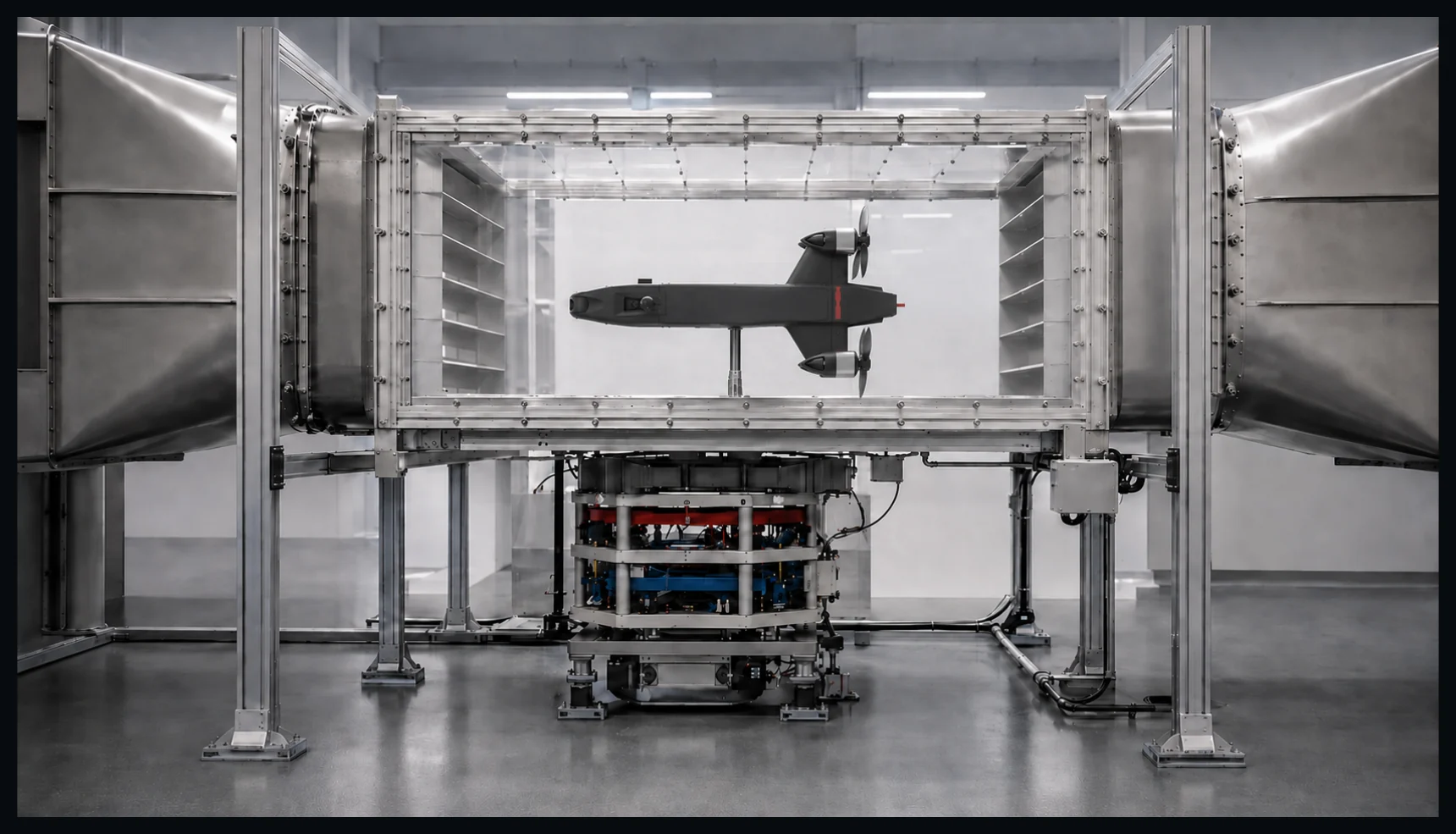
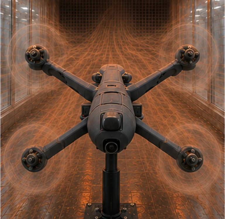
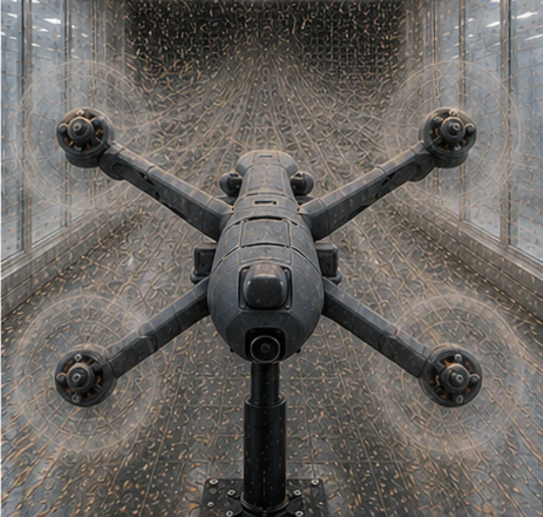
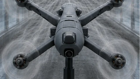
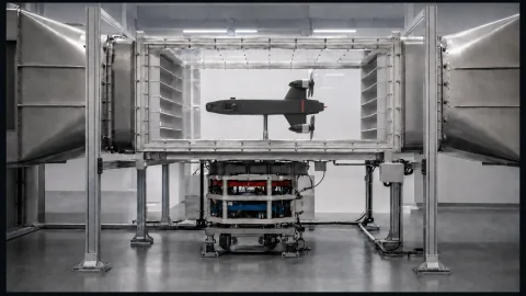
A TunnelTech projeta instalações personalizadas para VANTs (UAV) completos de pequeno porte, sistemas de propulsão, componentes e modelos em escala de aeronaves não tripuladas maiores.
As dimensões da seção de testes, as condições de escoamento, a instrumentação e os sistemas ambientais são definidos pelo objeto que você precisa testar e pelas evidências que precisa obter.
Um envelope de testes escalável, projetado em torno do programa
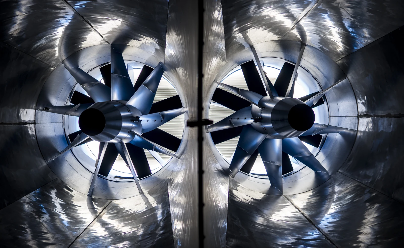
A TunnelTech aplica sua experiência em sistemas de fluxo de ar de grande escala e alta velocidade a uma nova geração de túneis de vento para testes de VANTs e pesquisa aerodinâmica.
Nossa tecnologia de paraquedismo indoor já opera com volumes de fluxo de ar utilizáveis excepcionalmente grandes em velocidades em torno de 300 km/h, incluindo câmaras de voo de até 6,5 m de diâmetro. Isso fornece uma base sólida de engenharia para instalações de testes de aeronaves não tripuladas, sistemas de propulsão e componentes aerodinâmicos.
Experiência de operaçãoComprovado
em escala industrial
01 / Velocidade do fluxo de ar
300+km/h
Comprovado em sistemas de fluxo de ar vertical em operação.
02 / Diâmetro de fluxo de ar utilizável
6,5m
Escala da câmara de voo comprovada em tecnologia entregue.
Regime de escoamento / 01
Túneis de vento de baixa velocidade
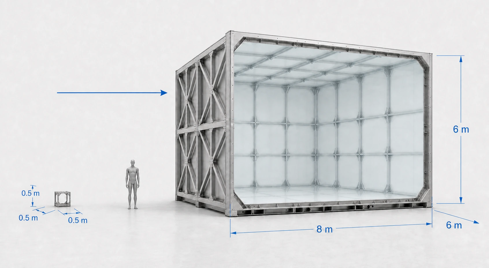
Velocidade do ar0–300km/h
Envelope de MachAté aproximadamente M 0,25
Faixa da seção de testes0,5 × 0,5 × 0,5 ma8 × 6 × 6 m
Projetado para
Testes de VANTs em tamanho real
VANTs de asa fixa
Aeronaves multirrotor e VTOL
Testes de hélices e sistemas de propulsão
Modelos aerodinâmicos em grande escala
Estudos de desempenho, estabilidade e controle
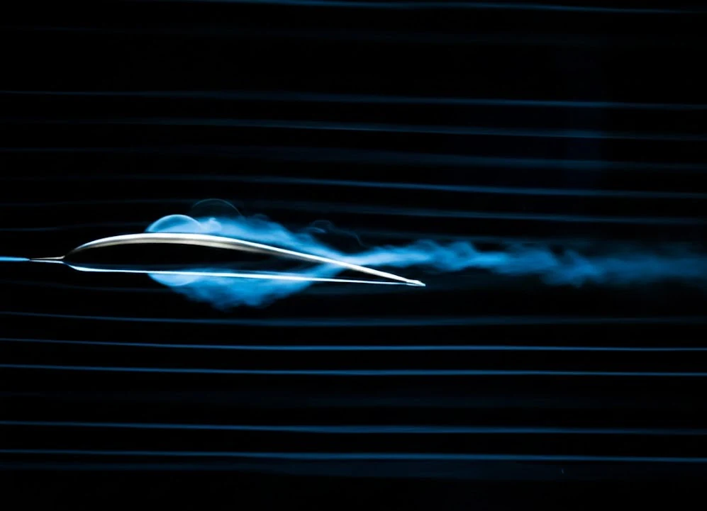
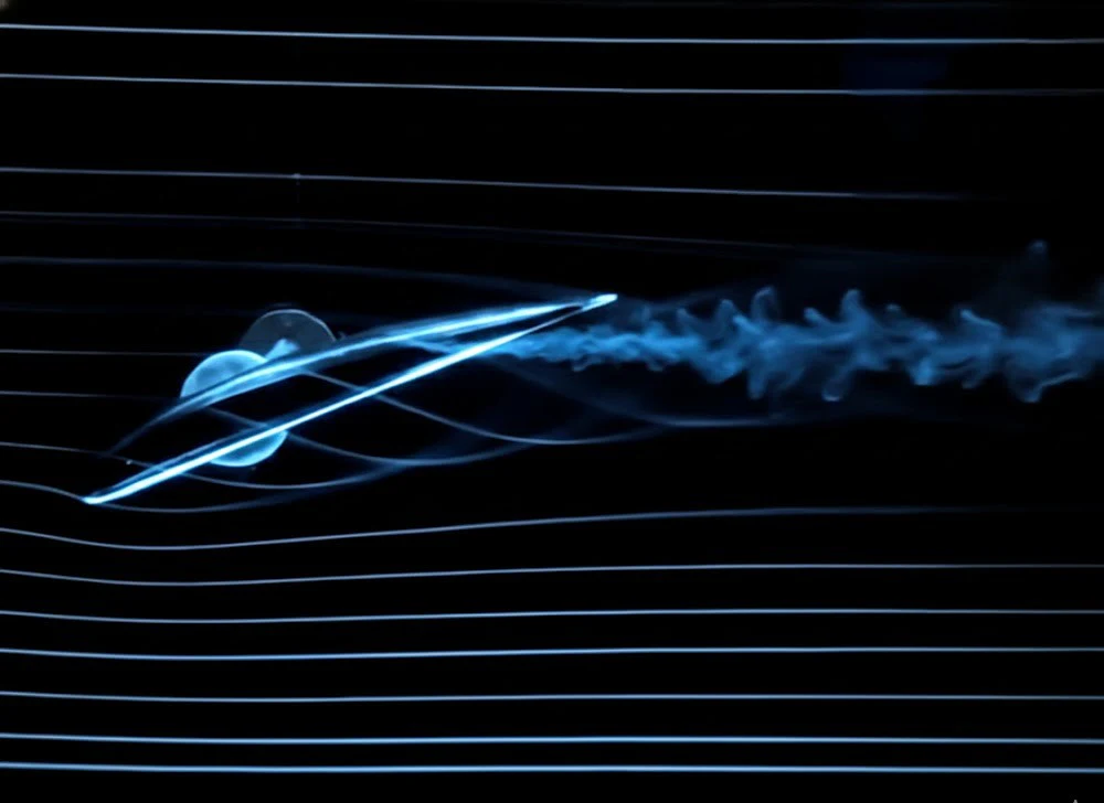
Visualização de escoamento e desenvolvimento aerodinâmico
Grandes seções de testes permitem que as aeronaves sejam testadas em tamanho real ou próximo a ele, reduzindo os efeitos de escala do modelo e melhorando a similaridade do número de Reynolds com as condições reais de voo.
Regime de escoamento / 02
Túneis de vento subsônicos de alta velocidade
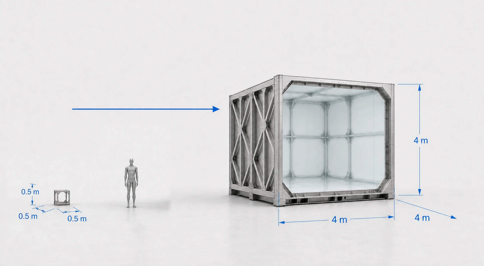
Velocidade do ar300–800km/h
Envelope de MachAproximadamente M 0,25–0,65
Faixa da seção de testes0,5 × 0,5 × 0,5 ma4 × 4 × 4 m
Projetado para
Desenvolvimento de VANTs de alta velocidade
Testes de VANTs em escala e em tamanho real
Pesquisa aerodinâmica subsônica alta
Desenvolvimento de asas, fuselagem e superfícies de controle
Testes de propulsão e admissão de ar
Testes de componentes aerodinâmicos
Estudos de estabilidade e desempenho em alta velocidade
As dimensões da seção de testes e a velocidade máxima estão intimamente interligadas. A demanda de potência, as cargas aerodinâmicas e os requisitos de condicionamento de escoamento aumentam rapidamente com a velocidade do ar, de modo que cada instalação é otimizada em torno do tamanho, velocidade e qualidade do escoamento exigidos.
Ambas as comparações de escala usam a mesma figura humana de 1,8 m, de modo que os dois envelopes da seção de testes podem ser lidos um em relação ao outro diretamente.
Envelope de engenharia indicativo, não uma especificação de catálogo. A velocidade máxima do ar, as maiores dimensões da seção de testes e a faixa de Mach não estão necessariamente disponíveis simultaneamente. O desempenho final depende da geometria da seção de testes, configuração do circuito, condições ambientais, potência e qualidade do escoamento exigida.
Fluxo de ar em grande escala / competência central
O grande fluxo de ar é a base. A qualidade da medição define a instalação de pesquisa.
Túneis de vento para testes aerodinâmicos e túneis de vento para voo humano têm requisitos de engenharia diferentes. A expertise existente da TunnelTech em fluxo de ar de grande volume fornece a base de engenharia; o túnel de pesquisa é então desenvolvido em torno dos requisitos de calibração e fluxo de nível de medição.
Baixa intensidade de turbulênciaAlta uniformidade de velocidadeBaixa angularidade do escoamentoGradientes de pressão estática controladosGerenciamento da camada limiteBaixa interferência de paredeMedição precisa de força e momentoCondições de calibração repetíveis
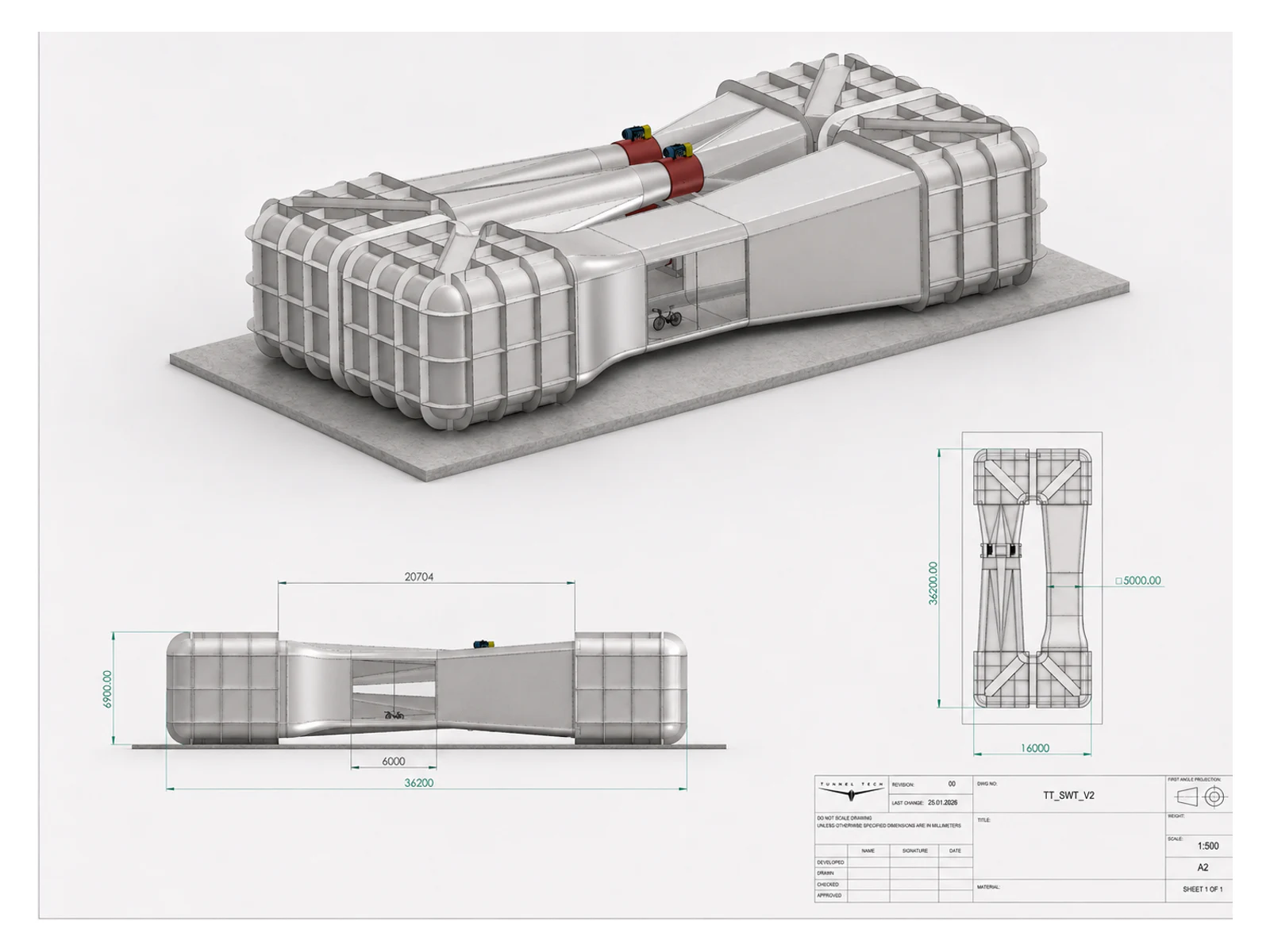
De túneis compactos de P&D a grandes instalações para aeronaves completas, cada sistema é projetado em torno do envelope de testes exigido pelo cliente.
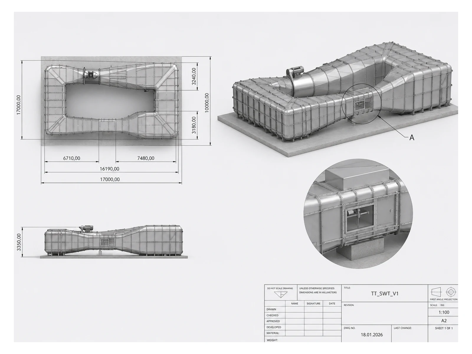
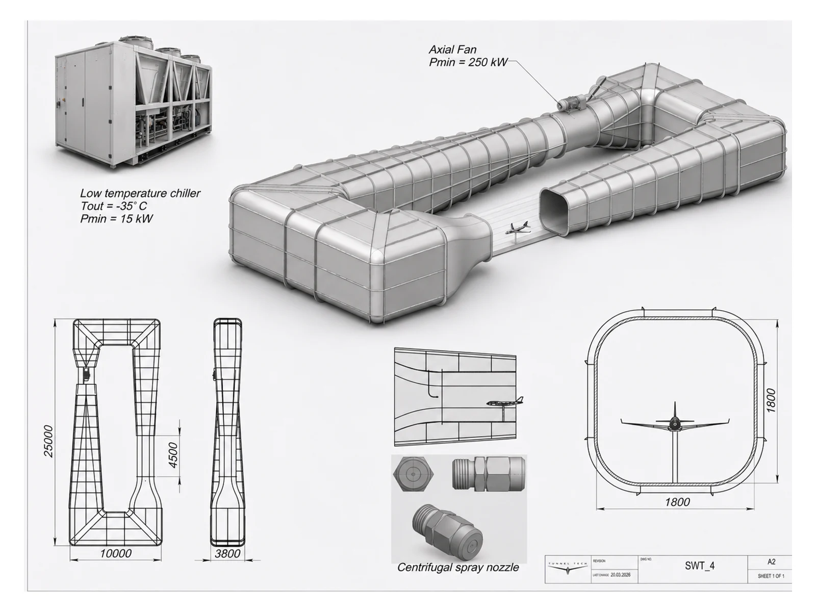
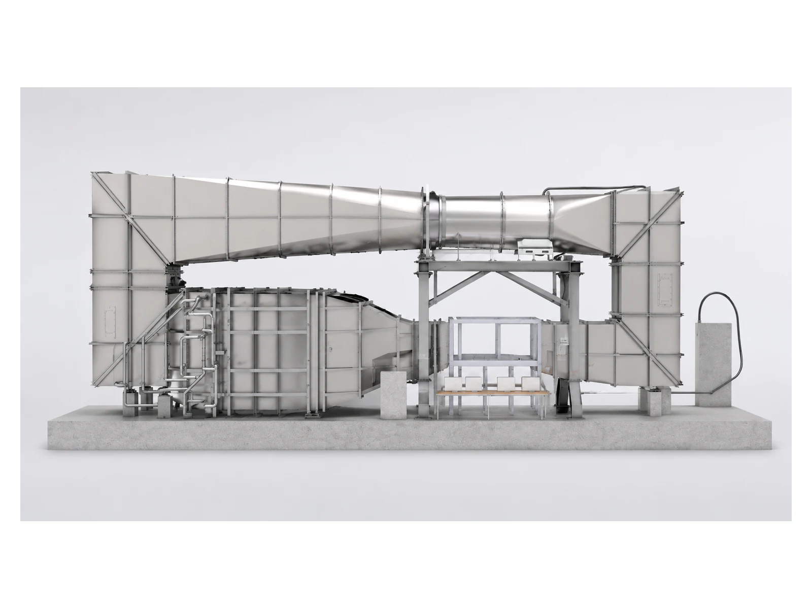
Exemplos de configurações de túnel de vento desenvolvidas para diferentes objetivos de pesquisa.
Configuração de pesquisa compactaPara componentes, conjuntos de propulsão e VANTs completos de pequeno porte, onde o acesso preciso e a repetibilidade importam mais do que construir um grande circuito.
Configuração maior para aeronaves completasPara o desenvolvimento de aeronaves completas, estudos de interação de rotores e modelos em escala que exigem mais espaço livre, menor bloqueio e instrumentação expandida.
Configuração com capacidade climáticaUm circuito horizontal com sistemas integrados de resfriamento e fornecimento de meios para condições de teste ambiental específicas do programa.
Configuração de retorno verticalUm circuito de retorno disposto verticalmente reduz a pegada horizontal onde a área útil é limitada, trocando a área ocupada pela altura disponível do edifício.
Apenas projetos conceituais. As dimensões mostradas nos desenhos ilustram layouts preliminares e não definem modelos de catálogo. A geometria final, o desempenho do escoamento e a arquitetura do sistema são estabelecidos durante a engenharia do projeto.
Construído em torno da matriz de testes
A instalação começa com o que você precisa medir
O circuito pode ser aberto ou fechado, compacto ou em escala de edifício. O que permanece constante é a sequência de engenharia: definir o objeto de teste, estabelecer o envelope de escoamento, controlar a interferência e integrar a cadeia de medição.
Objeto de teste
VANTs completos, rotores, hélices, sistemas de propulsão, cargas úteis, sensores e fuselagens em escala.
Envelope de escoamento
Faixas de velocidade constante, vento cruzado, rajadas, cisalhamento, turbulência e perfis transitórios específicos da missão.
Projeto da seção de testes
Geometria, acesso, suporte do modelo, acesso óptico e bloqueio gerenciados ao redor da aeronave.
Integração da instalação
Potência de acionamento, acústica, resfriamento, controles, sistemas de segurança e interfaces com o edifício do cliente.
TunnelTech + EVG Lufttechnik
Engenharia de túneis de vento apoiada pela fabricação de ventiladores industriais
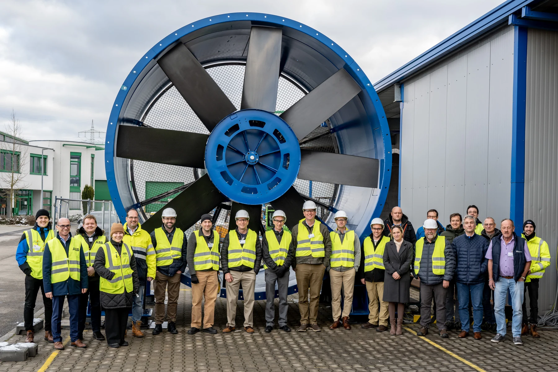
A TunnelTech é acionista da EVG Lufttechnik GmbH, nossa parceira estratégica de longa data. A EVG atua na engenharia de ventiladores industriais desde 1977 e fabrica ventiladores axiais desde 1987.
Essa base compartilhada de engenharia e fabricação dá a cada projeto acesso direto à seleção de ventiladores, dutos, condicionamento de escoamento, acústica, controles e operação industrial de alto rendimento.
Desde 1977Engenharia de ventiladores industriais
Desde 1987Fabricação de ventiladores axiais
StuttgartEngenharia e produção
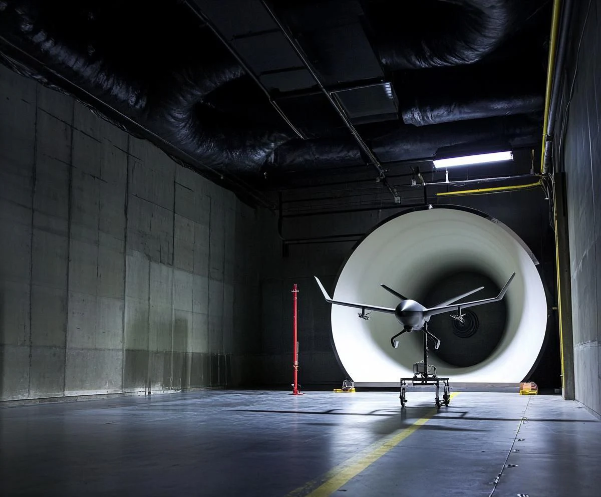
Testes de VANTs interceptadores de alta velocidade
Testes motorizados para VANTs interceptadores se aproximando de 500 km/h
Plataformas interceptadoras rápidas estão surgindo como uma resposta fundamental contra sistemas aéreos não tripulados (UAS). Nessas velocidades, propulsão, resfriamento, cargas estruturais e autoridade de controle deixam de se comportar como problemas separados e devem ser avaliados como um sistema acoplado, com potência, na seção de testes.
Envelope de testes até
500km/h
Propulsão sob carga aerodinâmica, medida com o motor em funcionamento
Estabilidade e autoridade de controle em todo o envelope da missão
Comportamento da admissão, do motor e térmico em alta velocidade sustentada
Opções ambientais
O fluxo de ar limpo é apenas o ponto de partida
Onde o programa exigir, sistemas ambientais podem ser projetados no circuito desde o início. A combinação final depende da matriz de testes, faixa de temperatura, manuseio de meios e requisitos de medição.
Perfis de ventoEscoamento constante, rajadas, vento cruzado, cisalhamento e turbulência.Exposição à águaChuva, pulverização e fornecimento de água específico do programa.Areia e poeiraEscoamento carregado de partículas com recuperação e filtragem projetadas para o meio.Frio e formação de geloControle de temperatura e condições de pulverização calibradas onde necessário.Condicionamento térmicoFaixas de operação quentes e frias para propulsão, baterias e eletrônicos.Cargas combinadasCombinações específicas do projeto desenvolvidas como uma função integrada da instalação.
Integração de medição
A instrumentação segue a pergunta, não um pacote padrão
Dependendo do programa, a instalação pode acomodar balanças de força multieixos, medição de pressão, visualização de escoamento, imagens de alta velocidade, PIV, suportes de modelo rotativos e aquisição de dados específica do cliente.
Equipamentos, fornecedores, metas de precisão e interfaces são definidos durante a engenharia do projeto e integrados à seção de testes como uma única cadeia de medição.
A instrumentação descrita aqui representa as opções de integração disponíveis. O equipamento final é selecionado para cada projeto.
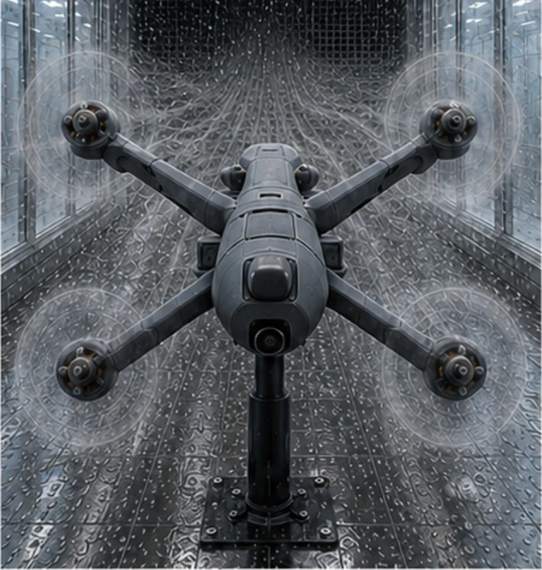
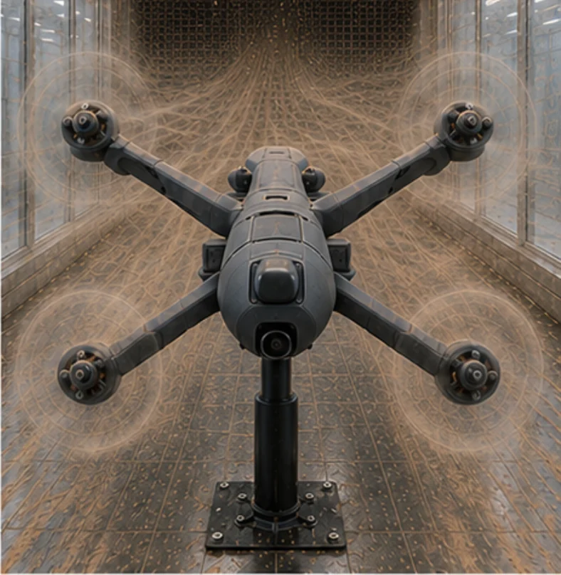
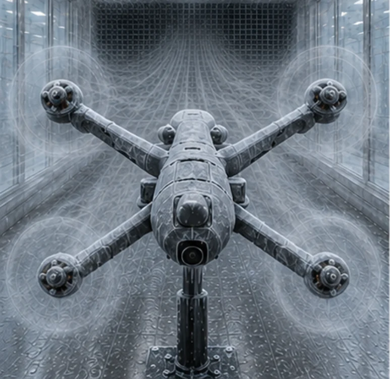
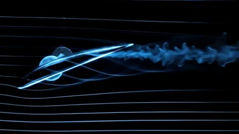
Visualização do escoamento / vista de perfil
Fabricação real. Locais de projeto reais.
Novas aplicações de VANTs. Engenharia e fabricação comprovadas.
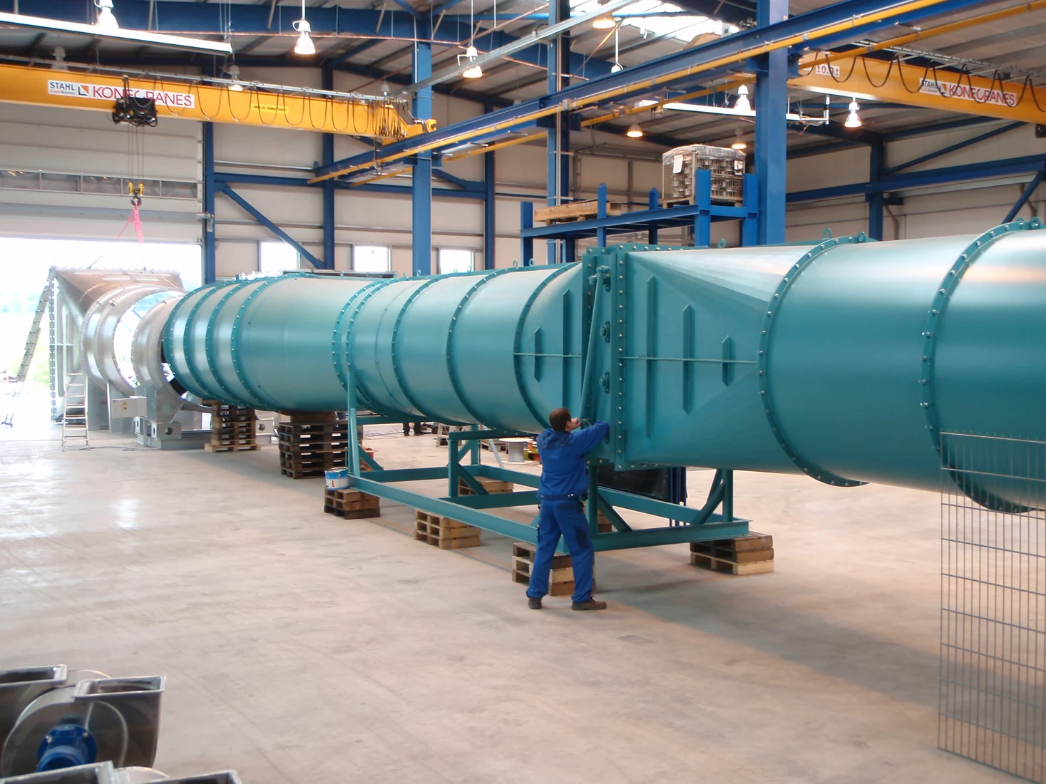
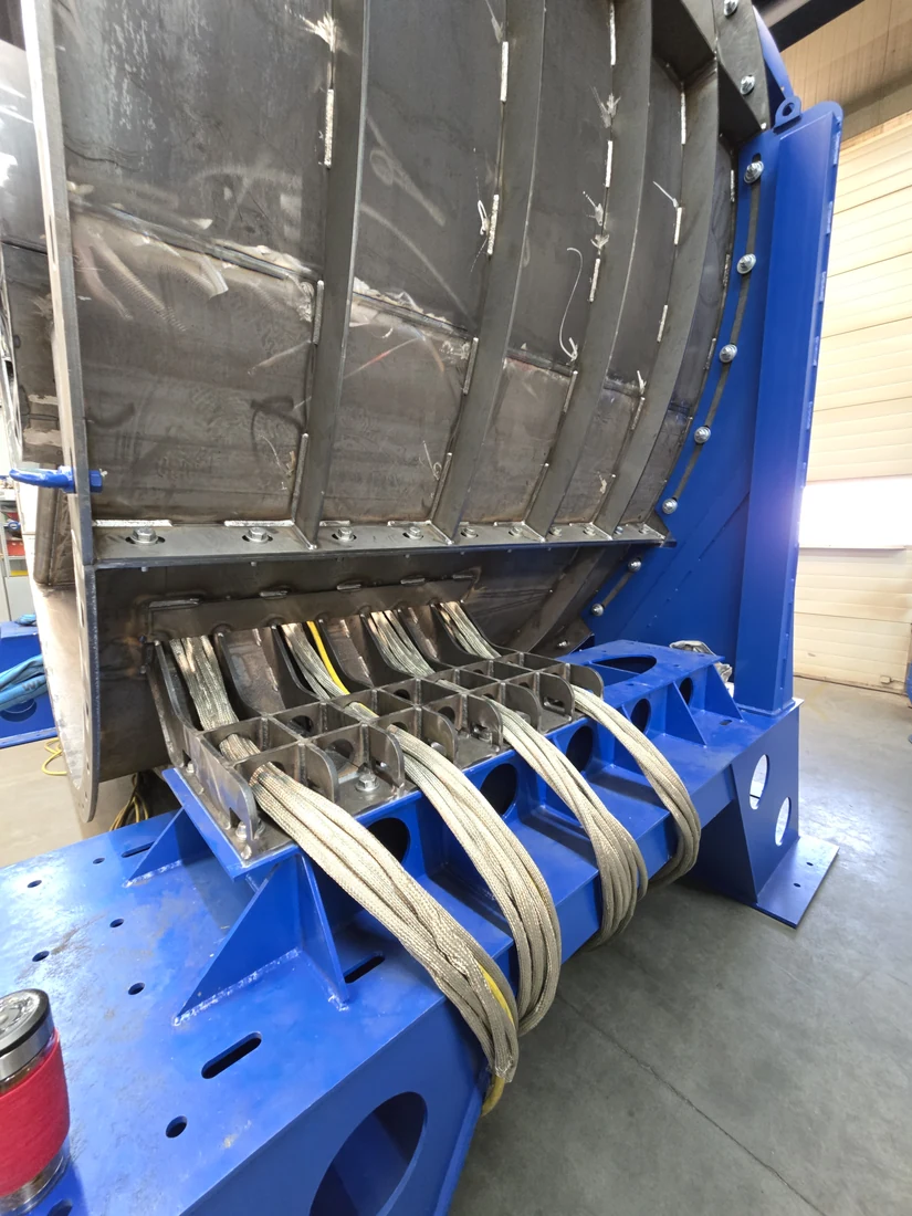
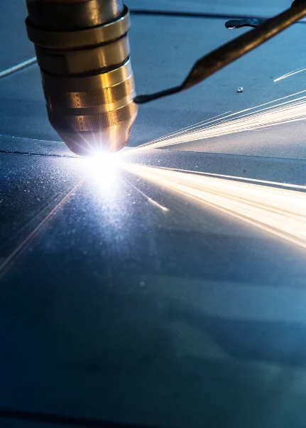
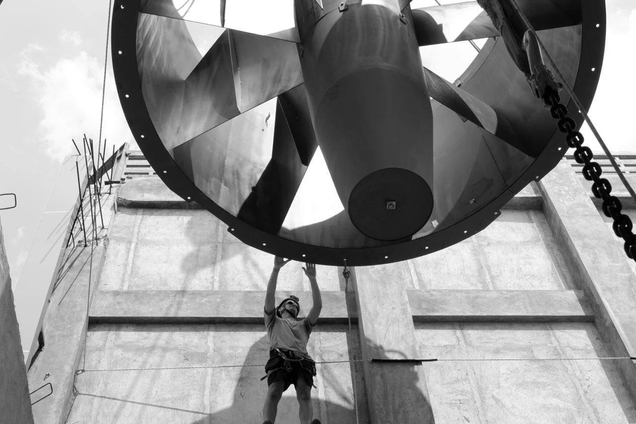
Trabalho real de fabricação em Stuttgart e trabalho de instalação de projetos de túnel de vento entregues em todo o mundo pela TunnelTech.
Fabricação de dutos em grande escala na EVGFabricação de componentes para serviço pesadoCorte a laser de componentes estruturais do túnel, StuttgartTrabalho de instalação em um local de projeto internacionalSistemas de ventiladores instalados em um projeto da TunnelTech
Responsabilidade centralizada do projeto
Do requisito de teste a uma instalação operacional
1
Análise de necessidades
Objetos de teste, medições, faixa de escoamento e restrições do local.
2
Conceito aerodinâmico
Arquitetura do circuito, seção de testes e demanda do sistema de ventiladores.
3
Engenharia mecânica
Estrutura, acústica, sistemas climáticos, controles e segurança.
4
Fabricação e integração
Fabricação, montagem em fábrica e integração de interfaces.
5
Instalação e comissionamento
Montagem no local, start-up, medição e aceitação.
6
Treinamento e suporte ao ciclo de vida
Treinamento de operadores, serviço, peças de reposição e atualizações futuras.
Responsabilidade centralizada, interfaces claras e suporte de longo prazo.